|
Home / Examples / Electromagnetic Analysis [Hertz] / Example 31: Murata's RF Inductor
Example 31: Murata's RF Inductor
General
-
The data is available from Murata's web site.
-
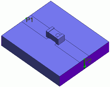
S-parameters of an RF inductor placed on a substrate are solved.
-
Microstrip lines connect the inductor's electrodes and the ports on the substrate.
-
Obtain this session's project file. (Right-click and choose 'Save link as')
-
Results will vary depending on Femtet version and the PC environment.
Analysis Space
|
Item |
Settings |
|
Analysis Space |
3D |
|
Model Unit |
mm |
Analysis Conditions
|
Item |
Settings |
|
Solver |
Electromagnetic Analysis [Hertz] |
|
Analysis Type |
Harmonic Analysis |
Harmonic Analysis tab and Open Boundary tab are set as follows.
|
Tab |
Setting Item |
Settings |
|
Mesh |
Element Type |
2nd-order Element |
|
Adaptive Meshing |
Select [Apply adaptive meshing]. |
|
|
Frequency-Dependent Meshing |
Reference Frequency: 5x10⁹ [Hz] Select [The conductor bodies thicker than the skin depth constitute the boundary condition]. |
|
|
Harmonic Analysis |
Sweep Type |
Select [Log Step] |
|
Sweep Values |
Minimum: 1x10⁹ [Hz] Maximum: 10x109 [Hz] Number of Divisions: 10 |
|
|
Sweep Setting |
Select Fast Sweep S-parameter Tolerance: 1x10⁻³ |
|
|
Input |
1.0 [W] |
|
|
Open boundary |
Types |
Absorbing boundary |
|
Order of Absorbing Boundary |
1st-order |
Model
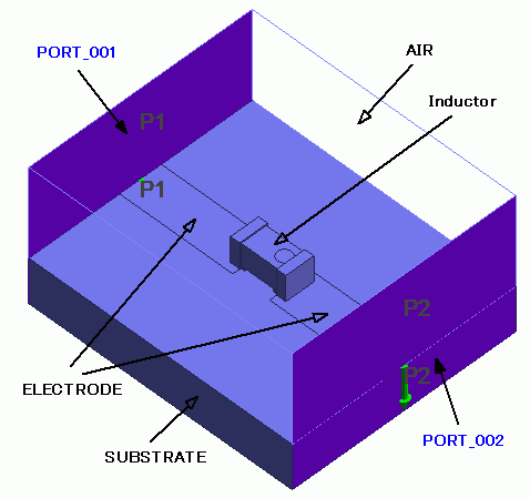
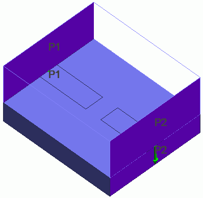
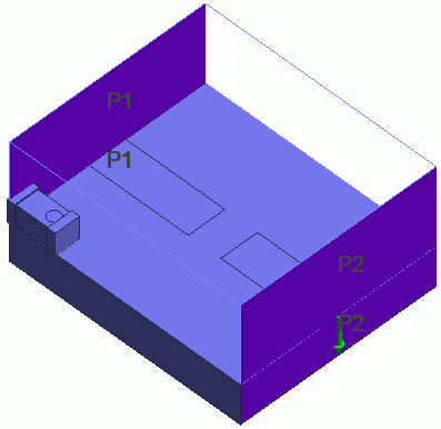
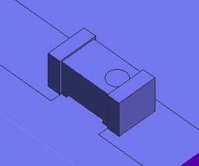
An RF inductor is placed on a substrate. Microstrip lines connect the inductor's electrodes and the ports on the substrate.
Ports are set on outermost faces.
| Whole Model | RF inductor (LQP02TN_02, LQP03TG_02 and LQP03TN_02 series) |
RF inductor (LQP02TQ_02 and LQP03HQ_02 series) |
 |
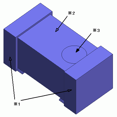 *1 External electrodes *2 Main body *3 Marking (indicates the top face) |
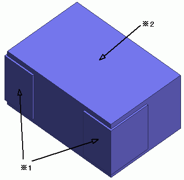 *1 External electrodes *2 Main body |
Model Creation
|
|
|
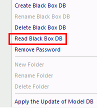 |
|
 |
|
 |
|
 |
Body Attributes and Materials
|
Body Number/Type |
Body Attribute Name |
Material Name |
|
0/Solid |
SUBSTRATE |
006_Glass_epoxy *1 |
|
1-2/Sheet |
ELECTRODE |
003_Ag *1 |
|
3/Solid |
Inductor *2 |
Inductor *2 |
|
4/Solid |
AIR |
000_Air(*) |
*1 Available from the material DB.
*2 Imported CAE data
The body attributes and material properties related to the inductor will be replaced by the black box data when the solver runs. Therefore the settings here are irrelevant.
Boundary conditions
|
Boundary Condition Name/Topology |
Tab |
Boundary Condition Type |
Settings |
|
Port_001/Face |
Electric |
Port |
|
|
Port_002/Face |
Electric |
Port |
|
|
Outer Boundary Condition |
Electric |
Electric Wall |
|
Results
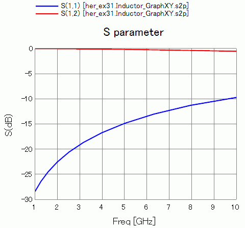
The frequency responses of S11 and S22 are shown below.