


|
Home / Examples / Electromagnetic Analysis [Hertz] / Example 38: TDR Analysis with Transient Analysis
Example 38: TDR Analysis with Transient Analysis
General
-
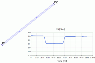
The inputs of impulse wave and stepped wave are used for the TDR analysis.
-
Unless specified in the list below, the default conditions will be applied.
-
Obtain this session's project file. (Right-click and choose 'Save link as')
-
Results will vary depending on Femtet version and the PC environment.
The project file contains analysis models with impulse input (Inpuls) and stepped-wave input (Step). -
Electromagnetic-transient analysis is available in an optional package.
Analysis Conditions
|
Item |
Settings |
|
Solver |
Electromagnetic Analysis [Hertz] |
|
Analysis Space |
3D |
|
Analysis Type |
Transient Analysis Select Input at each port |
|
Unit |
mm |
|
Tab |
Setting Item |
Settings |
|
Mesh |
General Mesh Size |
0.5 [mm] *1 |
|
Frequency-Dependent Meshing |
|
|
|
Transient Analysis |
Input Waveform |
Impulse Model
Step Model *2
|
|
Finish Time of Calculation |
1.0×10⁻⁹ [s] |
*1 Small general mesh size is set because fine meshes are needed for the entire transmission line.
*2 To reproduce the stepped waveform in the Step model, the same time is set for the duration and the finish time of calculation.
Model
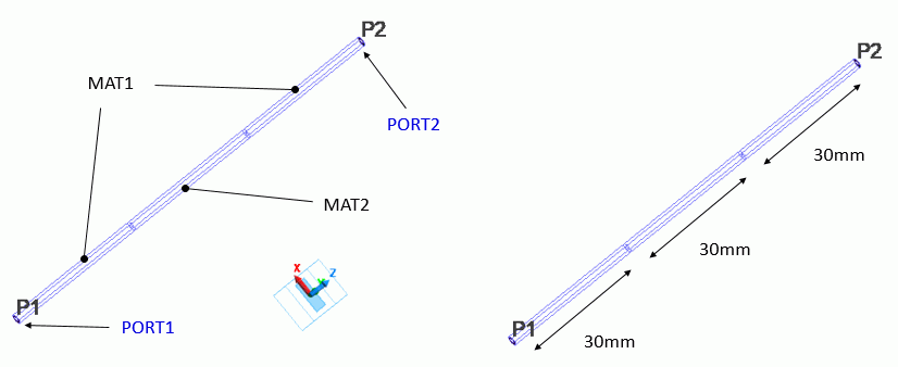
A coaxial cable consists of two insulators with different permittivity. For the outer boundary condition, electric wall is applied to the inside and outside of the cable.
The relative permittivity values for MAT1 and MAT2 are set so as to give them an impedance of about 50 [Ω] and 30 [Ω], respectively.
Body Attributes and Materials
|
Body Number/Type |
Body Attribute Name |
Material Name |
|
Body10/Solid |
MAT1 |
MAT1 |
|
Body11/Solid |
MAT1 |
MAT1 |
|
Body12/Solid |
MAT2 |
MAT2 |
|
Material Name |
Tab |
Properties |
|
MAT1 |
Permittivity |
Relative Permittivity: 1.0 |
|
MAT2 |
Permittivity |
Relative Permittivity: 2.8 |
Boundary Condition
|
Boundary Condition Name/Topology |
Tab |
Boundary Condition Type |
Settings |
|
PORT1/Face |
Electric |
Port |
Integral Path:
Reference Impedance: select
|
|
PORT2/Face |
Electric |
Port |
Integral Path:
Reference Impedance: select
|
|
Outer Boundary Condition |
Electric |
Electric Wall |
Results
The input/output voltage and TDR of the ports are confirmed in the result table of electromagnetic analysis (time domain).
Impulse model
The input voltage and the output voltage at PORT1 are as in the Fig. 1.
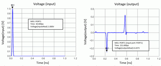
Fig. 1: The input and output voltage at PORT1
For the input of 1 [V], the reflection is -0.247 [V] at about 230[ps]. As the peak of the input wave is at 30[ps], it can be said that the input electromagnetic wave is reflected at the border of MAT1 and MAT2 where the impedances are unmatched.
The reflected wave take 200 [ps] to return.
These values can be estimated and verified in the following way.
- The traveling distance until coming back to PORT1 after reflected at the unmatched portion is 60mm.
The propagation speed of the electromagnetic wave in MAT1 is 3.0 x 10⁸ [m/s].
The time until the reflected wave returns to PORT1 is 60 mm / 30 x 10 8 [m/s] = 200 [ps].
- Characteristic impedance of PORT1 and coaxial cable of MAT2 are about 50 [Ω] and 30[Ω], respectively.
The reflectance is (30 - 50) / (30 + 50) = -0.25. Therefore, the reflection of the input of 1V will be -0.25 V.
From TDR of the result table (Fig. 2), it is confirmed that the characteristic impedance of the coaxial cable of MAT2 is 30 [Ω].
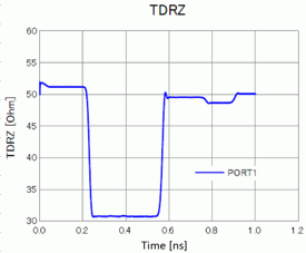
Fig. 2: TDR of PORT1 (Impulse model)
Step model
The similar result is obtained with the step model. The stepped wave rises more rapidly than the impulse wave and its TDR changes faster than that of the impulse.
It can be confirmed as shown in Fig. 3.
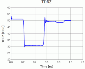
Fig. 3: TDR of PORT1 (Step model)