


|
Home / Examples / Electromagnetic Analysis [Hertz] / Example 44: Thin Electrode Elements
Example 44: Thin Electrode Elements
General
-
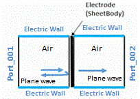
The analysis with thin electrode elements is performed. See [Thin Electrode Elements] for more information.
-
Thin Electrode Elements Model: Create a sheet body and set the material and the body attribute (sheet thickness) to the sheet body.
-
For the analysis with the electrode thickness taken into account, select [Take into account thickness of face/edge electrode].
-
Unless specified in the list below, the default conditions are applied.
-
Obtain this session's project file. (Right-click and choose 'Save link as')
-
Results will vary depending on Femtet version and the PC environment.
-
This example uses the waveguide of parallel plates. Please note that the outer boundary condition is changed to the magnetic wall.
Analysis Conditions
|
Item |
Settings |
|
Solver |
Electromagnetic Analysis [Hertz] |
|
Analysis Space |
3D |
|
Analysis Type |
Harmonic Analysis |
|
Unit |
mm |
|
Analysis Options |
Electrode Setting Select [Take into account thickness of face/edge electrode]. * |
Harmonic Analysis tab and Open Boundary tab are set as follows.
|
Tab |
Setting Item |
Settings |
|
Harmonic Analysis |
Frequency |
1 [MHz] |
|
Sweep Type |
Single Frequency |
|
|
Sweep Setting |
Discrete sweep |
|
|
Input |
1.0 [W] |
Model
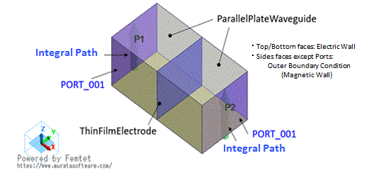
The waveguide of parallel plates is modeled to analyze the propagation of plane waves.
Boundary conditions are set as follows.
Point 1: The outer boundary condition is changed to the magnetic wall.
Point 2: The top and bottom faces are set with the electric wall.
Body Attributes and Materials
|
Body Number/Type |
Body Attribute Name |
Material Name |
|
0/Solid |
ParallelPateWaveguide |
000_Air * |
|
1/Solid |
ParallelPateWaveguide |
000_Air * |
|
2/Sheet |
ThinFilmElectrode |
METAL |
* Available from the material DB
|
Body Attribute Name |
Tab |
Material Name |
|
ThinFilmElectrode |
Thickness/Width |
1.×10-5 [mm] |
|
Material Name |
Tab |
Properties |
|
METAL |
Permittivity |
Relative Permittivity: 1.0 |
|
Permeability |
Relative Permeability 1.0 |
|
|
Electric Conductivity |
Select [Conductor]. Conductivity: 1.e7 |
Boundary Conditions
|
Boundary Condition Name/Topology |
Tab |
Boundary Condition Type |
Settings |
|
EW/Face |
Electric |
Electric Wall |
|
|
Port_001/Face |
Electric |
Port |
Reference Impedance: [Use the characteristic impedance calculated from the port structure]. |
|
Port_002/Face |
|||
|
Outer Boundary Condition * |
Electric |
Magnetic Wall |
|
* Although the default setting of the outer boundary condition is the electric wall, the magnetic wall is used here.
Results
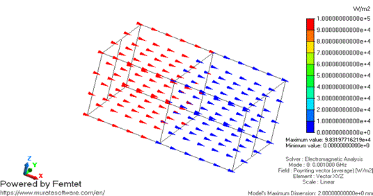
Poynting vectors on average are shown below. The color of the arrow indicates the magnitude of the Poynting vector.
The color changes from red to blue across the thin electrode, indicating the magnitude decreases.
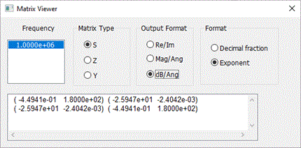
Examine the S-parameters of the waveguide.
[Results]>[Show Results]>[Show Characteristics Chart]>[SYZ Matrix]>[View]>[Matrix Viewer],
S-parameters are displayed.
S21 of -26 [dB] indicates that the electromagnetic waves pass through the thin electrode elements.
If the electromagnetic waves fail to pass through, the model may not be set properly.
Please check whether [Take into account thickness of face/edge electrode] is selected.
See [Thin Electrode Elements] of technical note for comparison with theoretical values.