


|
Home / Examples / Electromagnetic Analysis [Hertz] / Example 46: Skin Depth
Example 46: Skin Depth
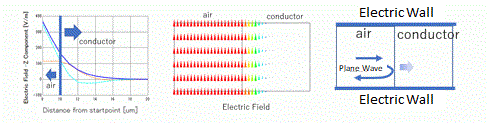
General
-
It is confirmed that the skin depth calculated by Femtet matches the theoretical values.
-
Unless specified in the lists below, the default conditions will be applied.
-
Obtain this session's project file. (Right-click and choose 'Save link as')
-
Theoretically, skin depth is given by the following equation. The conditions of the example will yield a skin depth of 2 um using the theoretical equation.
(Conditions: frequency = 1 GHz; conductivity = 6.289e7 S/m; relative permeability = 1)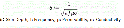 (1)
(1)
Analysis Condition
|
Item |
Settings |
|
Solver |
Electromagnetic Analysis [Hertz] |
|
Analysis Space |
3D |
|
Analysis Type |
Harmonic Analysis |
|
Unit |
mm |
Set the harmonic analysis and mesh tabs as follows.
|
Tab |
Setting Item |
Settings |
|
Harmonic Analysis |
Frequency |
1×10⁹ [Hz] |
|
Sweep Type |
Single Frequency |
|
|
Frequency Sweep |
Discrete Sweep |
|
|
Input |
1.0 [W] |
|
|
Mesh |
General Mesh Size |
1.0 |
|
Adaptive Mesh |
Deselect [Apply adaptive meshing]. |
|
|
Frequency-Dependent Meshing |
Deselect [The conductor bodies thicker than the skin depth constitute the boundary condition]. |
- To accurately calculate the attenuation of electromagnetic waves in a conductor, set the mesh size to half the skin depth.
- Deselect [Apply adapting meshing] since the electromagnetic field distribution is known in advance.
-
Deselect [The conductor bodies thicker than the skin depth constitute the boundary condition], since with this option selected, you will not be able to observe electromagnetic fields entering the conductor.
Model
The waveguide of parallel plates is modeled to propagate plane waves. When a plane wave is incident on a conductor, most of the wave is reflected from the conductor, but a small amount is incident.
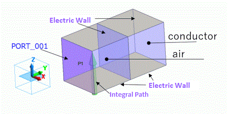
Body Attributes and Materials
|
Body Number/Type |
Body Attribute Name |
Material Name |
|
0/Solid |
air |
000_Air * |
|
1/Sheet |
conductor |
003_Ag * |
* Available from the material DB
Boundary Conditions
|
Boundary Condition Name/Topology |
Tab |
Boundary Condition Type |
Settings |
|
PORT/Face |
Electric |
Port |
Reference Impedance: Select
Number of Modes: Number of Precalculated Modes: 5 Number of Modes Used in the Actual 3D Analysis: 1 Select Modes: None |
|
Outer Boundary Condition |
Electric |
Magnetic Wall |
Results
How to check skin depth is shown below.
Fig. 1 illustrates the electric field vectors of the result fields, indicating a slight penetration of electric fields into the conductor.
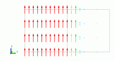
Fig. 1 Electric Field Vectors (Phase 0)
The contour of the absolute Z-component of an electric field is shown and its graph is illustrated below (Fig. 2).
The left figure of Fig. 2 shows the setting for the graph. The starting and ending points of the graph are positioned at the positions on the right figure of Fig. 2.
The starting and ending points are positioned at the surface of the conductor and away from the surface, respectively. The graph, therefore, indicates the variation in the strength of the electric field inside the conductor.
The number of divisions is set to 1000. As skin depth is determined from the graph, the precision of the obtained skin depth depends on the number of divisions of the graph.
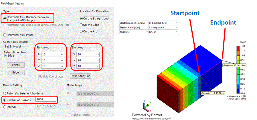
Fig2. Graph Setting
Fig. 3 indicates the graph depicted with the setting of Fig. 2, with markers added. Place a marker on the surface of the conductor and read the value.
The value of 163.296 V/m is given. The skin depth is the depth at which the magnitude of electric fields reduces to 1/e times. The position where the magnitude of electric fields is 60.0073 (=163.296/e) indicates the point at the skin depth.
The graph indicates the position is 2 um from the surface.
The calculation result matches the theoretical value.
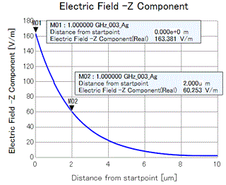
Fig.3 Calculation Result with Markers
Notes for Analysis
-
Determining a mesh size is important. In this example, where the skin depth is known, the mesh size can be set to half of the skin depth. If not, an optimal mesh size must be found.
-
Determining the analysis model size is also important. As explained above, the mesh size is determined based on the skin depth. If the model size is much larger than the skin depth, the calculation will require much more time for analysis.
-
In this example, cubic shapes of air and conductors are used for the models. However, an elongated model in the direction of electromagnetic wave propagation also allows for sufficient evaluation of the skin depth, resulting in a lower calculation load.
-
By setting Magnetic Wall to the exterior boundary condition, a plane wave can be excited.