|
Home / Examples / Magnetic Analysis (Luvens, Transient Analysis) / Example 3: Cogging Torque of Axial Gap Type Motor
Example 3: Cogging Torque of Axial Gap Type Motor
General
-
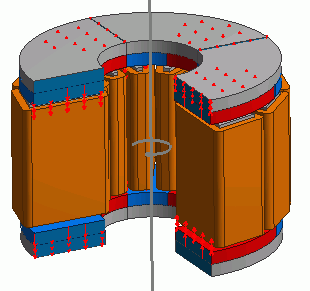
Axial gap type motor is analyzed.
Axial gap type motor consists of opposing disc type rotor and stator.
Cogging torque is analyzed which is generated by the rotor's rotation while no electricity is applied to the coils. -
Analysis function for axial gap motor is applied.
-
The cogging torque and the magnetic flux density are solved.
-
Unless specified in the list below, the default conditions will be applied.
-
Obtain this session's project file. (Right-click and choose 'Save link as')
-
Results will vary depending on Femtet version and the PC environment.
Analysis Conditions
|
Item |
Settings |
|
Solver |
Magnetic Analysis [Luvens] |
|
Analysis Space |
3D |
|
Analysis Type |
Transient Analysis |
|
Unit |
mm |
|
Options |
Select Rotating Machinery.
[Partial Model (Symmetric Model) Setting] Select Partial Model. Number of Divisions of Full Model: 4 Select Convert results to full model for output. |
The Rotating Machinery tab is set as follows.
|
Tab |
Setting Item |
Settings |
|
Rotating Machinery |
Rotational Movement |
Select Constant Velocity Number of Rotations: 1800 [r/min] Rotor’s Initial Rotation Position: 0 [deg] |
|
Gap Type |
Axial Gap |
|
|
Number of Sliding Mesh Divisions |
Circumferential Division Angle: 1.0 [deg] Rotational Quantity per Step: 1 [mesh] Number of Sliding Mesh Layers: 3 |
|
|
Location of Sliding Mesh |
Deselect Automatic Calculation Rotor Type: Outer Rotor
[Gap Radius] Inner: 110×10-3 [m] Outer: 112×10-3 [m]
[Gaps' Coordinates in Axial Direction] Top Side of Upper Gap: 52×10-3 [m] Bottom Side of Upper Gap: 50×10-3 [m] Top Side of Lower Gap: -50×10-3 [m] Bottom Side of Lower Gap: -52×10-3 [m]
|
|
|
Division Size of Sliding Mesh in the Axis Direction |
Divide at uniform interval with specified mesh size 10.0 [mm] |
Set the Mesh Tab as follows.
|
Tab |
Setting Item |
Settings |
|
Mesh |
Meshing Setup |
Automatically set the general mesh size: Deselect General Mesh Size: 7 [mm] |
|
Air Domain Creation |
Select Create air domain automatically Air Domain Scale: 1.2 |
The Transient Analysis tab is set up as follows.
With the settings as below, number of calculation steps is 90, circumferential division angle is 1.0 [deg], and rotational quantity per step is 1[mesh]. The rotation up to 90 degrees (=90*1.0*1) is analyzed.
|
Tab |
Setting Item |
Settings |
|||||
|
Transient Analysis |
Timestep |
Automatic |
|||||
|
Table |
|
Graphical Objects
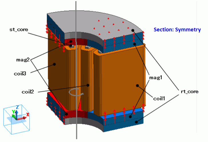
A rotor core and coils are placed between stator cores and permanent magnets.
By utilizing the symmetry of the analysis model, it is made to be a quarter model.
"Air Domain Creation" is selected.
-
It is assumed that coil1, 2, and 3 are made of fine copper wires which will have little effect of induced current. So, [No] is selected for the options of Induced Current.
If [Yes] is selected, the loss by induced current will affect the analysis and correct cogging torque will not be obtained.
Body Attributes and Materials
|
Body Number/Type |
Body Attribute Name |
Material Name |
|
34/Solid |
coil1 |
Cu |
|
35/Solid |
coil2 |
Cu |
|
36/Solid |
coil3 |
Cu |
|
33,37,38/Solid |
st_core |
core |
|
20,31/Solid |
mag1 |
mag |
|
19,30/Solid |
mag2 |
mag |
|
23,32/Solid |
rt_core |
core |
The material properties are set up as follows:
|
Body Attribute Name |
Tab |
Settings |
|
coil1 |
Current |
Induced Current: Deselect |
|
Stator/Rotor/Air |
Stator |
|
|
coil2 |
Current |
Induced current: deselect |
|
Stator/Rotor/Air |
Stator |
|
|
coil3 |
Current |
Induced Current: Deselect |
|
Stator/Rotor/Air |
Stator |
|
|
mag1 |
Direction |
Vector: X=0, Y=0, Z=1 |
|
Stator/Rotor/Air |
Rotor |
|
|
mag2 |
Direction |
Vector: X=0, Y=0, Z=-1 |
|
Stator/Rotor/Air |
Rotor |
|
|
rt_core |
Stator/Rotor/Air |
Rotor |
|
st_core |
Stator/Rotor/Air |
Stator |
The material properties are set as follows.
|
Material Name |
Tab |
Properties |
||||||||||||||||||||||
|
Cu |
Conductivity |
Conductivity Type: Conductor Conductivity: 5.977x10⁷ [S/m] |
||||||||||||||||||||||
|
mag |
Relative permeability |
Material Type: Permanent Magnet |
||||||||||||||||||||||
|
Magnet |
Magnetization Characteristic Type: Linear Magnetization Strength: 0.5 [T] Relative Permeability: 1.05 |
|||||||||||||||||||||||
|
core |
Permeability |
Magnetization Characteristic Type: Select B-H Curve
B-H Curve Table
|
Boundary Conditions
Symmetric period boundary is set.
|
Boundary Condition Name/Topology |
Tab |
Boundary Condition Type |
Settings |
|
Symmetry |
Symmetry/Continuity |
Periodic |
Rotation (Periodic) |
Results
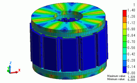
The distribution of the magnetic flux density at the rotation angle of 0[deg] is shown below.
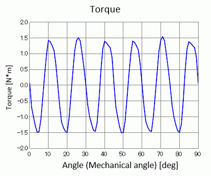
The waveform of cogging torque is shown as follows. It is output to [Torque [N*m]] of the result table.