|
Home / Examples / Magnetic Analysis (Luvens, Transient Analysis) / Example 4: Starting Characteristics of Induction Motor
Example 4: Starting Characteristics of Induction Motor
General
-
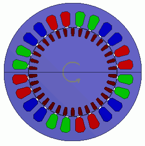
A 3-phase cage structure induction motor is analyzed.
The magnetic field of the coils on the outer stator induces the eddy current on the conductive rotor in the center.
The interaction between the magnetic fields caused by the eddy current and that of the stator generates a torque to rotate the asynchronous motor. -
The motion coupled analysis is applied.
-
The analysis begins from the stationary state of the model. The rotation is gradually increased and stabilized at about 1000[r/min].
-
The rotation velocity, torque and magnetic flux density are solved.
-
Unless specified in the list below, the default conditions will be applied.
-
Obtain this session's project file. (Right-click and choose 'Save link as')
-
Results will vary depending on Femtet version and the PC environment.
Analysis Conditions
|
Item |
Settings |
|
Analysis Space |
2D |
|
Thickness in Depth Direction |
42 [mm] |
|
Unit |
mm |
|
Solver |
Magnetic Analysis [Luvens] |
|
Analysis Type |
Transient Analysis |
|
Options |
Select External Circuit Coupling. Select Rotating Machinery.
[Partial Model (Symmetric Model) Setting] Select Partial Model. Number of Divisions: 2 [Conversion of external circuit I/O values] Select Convert Number of Series: 1 Number of Parallels: 2 Select Convert the result to the full model for output |
The Rotating Machinery tab is set as follows.
|
Tab |
Setting Item |
Settings |
|
Rotating Machinery |
Rotational Movement |
Select Motion Equation Coupling |
|
Number of Sliding Mesh Divisions |
Circumferential Division Angle: 0.5 [deg] Number of Sliding Mesh Layers: 3 |
|
|
Setting Motion Equation Coupling |
Moment of Inertia |
Inertial Moment of Rotor: 6.269×10⁻⁴ [kg*m2] Inertial Moment of Load: 3.0×10⁻³ [kg*m2] |
|
External Torque |
Waveform: Constant 0 [N*m] |
|
|
Coulomb Friction Torque |
Waveform: Coefficient Coulomb Friction Torque: 0.5×10⁻⁵ [N*m] Coefficient of Viscous Friction: 0 [N*m/(r/min)] Squared Coefficient of Load Torque: 1.226×10⁻⁶ [N・m/(r/min)2] |
|
|
Initial Time State |
Number of Rotations: 0 [r/min] Rotor’s Initial Rotation Position: 0 [deg] |
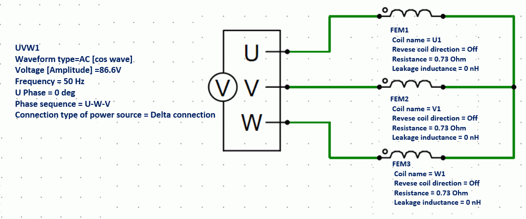
External circuit is as follows.
3-phase AC voltage of 50 [Hz] is applied.
Set the Mesh Tab as follows.
|
Tab |
Setting Item |
Setting |
|
Mesh |
Meshing Setup |
Automatically set the general mesh size: Deselect General Mesh Size: 2 [mm] |
|
Automatic Air Domain Creation |
Select Create air domain automatically Air Domain Scale: 1.2 |
The Transient Analysis tab is set up as follows.
One second is divided into 800 steps.
|
Tab |
Setting Item |
Settings |
|||||||
|
Transient Analysis |
Timestep |
Manual |
|||||||
|
Table |
|
Graphical Objects
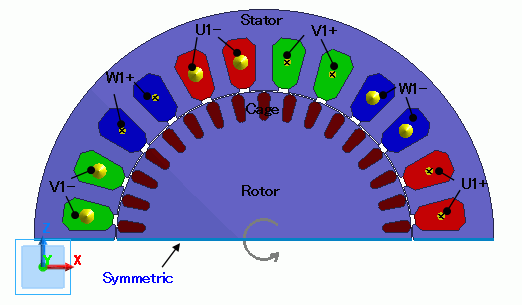
A rotor cage consisted of conductor and rotor core is placed in the center. A stator core and coils are placed around it.
This is a 2D analysis of a symmetric half model.
[Create air domain automatically] is selected.
Small mesh size (0.3 mm) is applied to the gap.
Body Attributes and Materials
|
Body Number/Type |
Body Attribute Name |
Material Name |
|
25/Sheet |
Cage |
Al |
|
26/Sheet |
Cage |
Al |
|
27/Sheet |
Cage |
Al |
|
28/Sheet |
Cage |
Al |
|
29/Sheet |
Cage |
Al |
|
30/Sheet |
Cage |
Al |
|
31/Sheet |
Cage |
Al |
|
32/Sheet |
Cage |
Al |
|
33/Sheet |
Cage |
Al |
|
34/Sheet |
Cage |
Al |
|
35/Sheet |
Cage |
Al |
|
36/Sheet |
Cage |
Al |
|
37/Sheet |
Cage |
Al |
|
38/Sheet |
Cage |
Al |
|
39/Sheet |
Cage |
Al |
|
40/Sheet |
Cage |
Al |
|
41/Sheet |
Cage |
Al |
|
24/Sheet |
Rotor |
50A1300 |
|
65/Sheet |
Stator |
50A1300 |
|
67/Sheet |
U1+ |
Cu |
|
68/Sheet |
U1+ |
Cu |
|
69/Sheet |
W1- |
Cu |
|
70/Sheet |
W1- |
Cu |
|
71/Sheet |
V1+ |
Cu |
|
72/Sheet |
V1+ |
Cu |
|
73/Sheet |
U1- |
Cu |
|
74/Sheet |
U1- |
Cu |
|
75/Sheet |
W1+ |
Cu |
|
76/Sheet |
W1+ |
Cu |
|
77/Sheet |
V1- |
Cu |
|
78/Sheet |
V1- |
Cu |
The material properties are set up as follows:
|
Body Attribute Name |
Tab |
Settings |
|
Cage |
Stator/Rotor/Air |
Rotor |
|
Rotor |
Stator/Rotor/Air |
Rotor |
|
Stator |
Stator/Rotor/Air |
Stator |
|
U1- |
Current |
Waveform: External Circuit Coupling Coil Name on the Circuit: U1 Turns: 66 [Turns] Direction: - Y Direction |
|
Stator/Rotor/Air |
Stator |
|
|
U1+ |
Current |
Waveform: External Circuit Coupling Coil name on the circuit: U1 Turns: 66[Turns] Direction: +Y Direction |
|
Stator/Rotor/Air |
Stator |
|
|
V1- |
Current |
Waveform: External Circuit Coupling Coil Name on the Circuit: V1 Turns: 66 [Turns] Direction: - Y Direction |
|
Stator/Rotor/Air |
Stator |
|
|
V1+ |
Current |
Waveform: External Circuit Coupling Coil name on the circuit: V1 Turns: 66 [Turns] Direction: +Y Direction |
|
Stator/Rotor/Air |
Stator |
|
|
W1- |
Current |
Waveform: External Circuit Coupling Coil Name on the Circuit: W1 Turns: 66 [Turns] Direction: - Y Direction |
|
Stator/Rotor/Air |
Stator |
|
|
W1+ |
Current |
Waveform: External Circuit Coupling Coil name on the circuit: W1 Turns: 66 [Turns] Direction: +Y Direction |
|
Stator/Rotor/Air |
Stator |
The material properties are set as follows.
|
Material Name |
Tab |
Properties |
||||||||||||||||||||||||||||||||||||||||||||||||||||||||||||||||||||||||||||||||||
|
Al |
Electric Conductivity |
Conductivity Type: Conductor Conductivity: 1.02x10⁷ [S/m] |
||||||||||||||||||||||||||||||||||||||||||||||||||||||||||||||||||||||||||||||||||
|
Cu |
Electric Conductivity |
Conductivity Type: Conductor Conductivity: 5.977x10⁷ [S/m] |
||||||||||||||||||||||||||||||||||||||||||||||||||||||||||||||||||||||||||||||||||
|
50A1300 |
Permeability |
Magnetization Characteristic Type: Select B-H Curve
B-H Curve Table
|
Boundary Conditions
Symmetric period boundary is set.
|
Boundary Condition Name/Topology |
Tab |
Boundary Condition Type |
Settings |
|
Symmetric |
Symmetry/Continuity |
Periodic |
Rotation (Periodic) |
Results
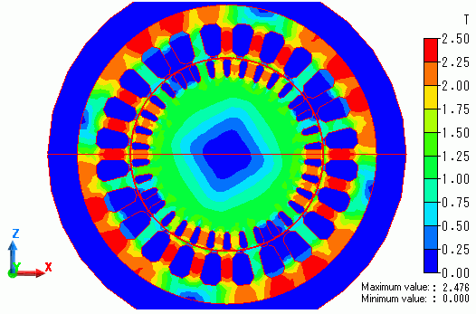
The distribution of the magnetic flux density right after the start is shown below.
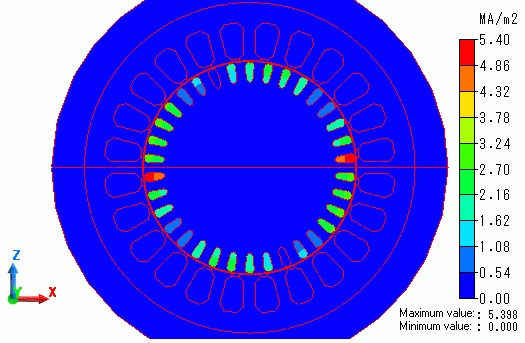
The distribution of eddy current density is shown as follows.
Eddy current is generated at the cage conductor by the magnetic flux created by the coils.
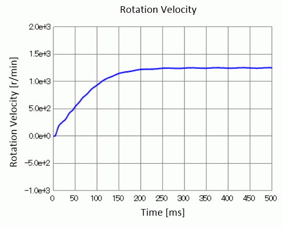
The diagram below shows time-rotation velocity characteristic.
The rotation is gradually increased and stabilized at about 1250 [r/min].
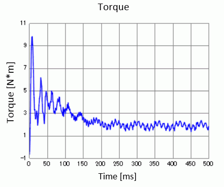
The diagram below shows time-torque characteristics. It is output to "Torque [N*m]" of the result table.