|
Home / Examples / Magnetic Analysis (Luvens, Transient Analysis) / Example 11: Magnetic Field Distribution of Coil Antenna with Capacitor for Resonance
Example 11: Magnetic Field Distribution of Coil Antenna with Capacitor for Resonance
General
-
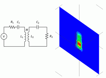
The model includes coils and external circuits. Magnetic field distribution at the LF band (around 130 kHz) is analyzed.
-
The magnetic flux density distribution, the circuit current, and the inductance are calculated.
-
The analysis is coupled with the external circuit.
Resonant capacitors are placed in the external circuit. -
Unless specified in the list below, the default conditions will be applied.
-
Obtain this session's project file. (Right-click and choose 'Save link as')
-
Results will vary depending on Femtet version and the PC environment.
Analysis Space
|
Item |
Settings |
|
Analysis Space |
3D |
|
Model Unit |
mm |
Analysis Conditions
|
Item |
Settings |
|
Solver |
Magnetic Analysis [Luvens] |
|
Analysis Type |
Transient Analysis |
|
Options |
Select [Inductance Calculation]. |
The Transient Analysis tab is set up as follows.
An analysis is performed for four cycles of a 50 kHz AC input.
To reproduce its waveform well, the timestep is set by dividing the periodic time of 50 kHz by the default value of 12.
|
Tab |
Setting Item |
Settings |
|
Transient Analysis |
Timestep |
Automatic |
|
Timestep Setting |
Number of Cycles 4 |
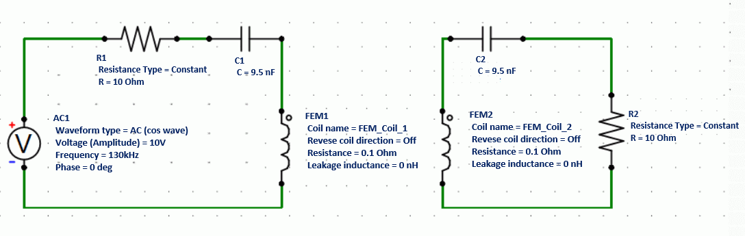
External circuit is as follows.
An AC power is placed on the primary side.
The primary coil and the secondary coil are connected on the model side.
The capacitors are connected to both of the primary and secondary coils in order to have the LC series resonance.
Model
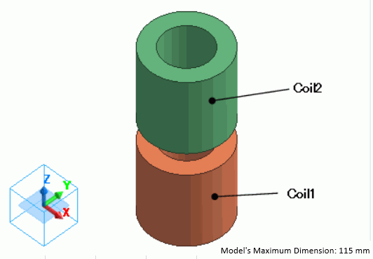
The primary coil (Coil1) and the secondary coil (Coil2) are defined by the loop coil.
Body Attributes and Materials
|
Body Number/Type |
Body Attribute Name |
Material Name |
|
5/Solid |
Coil1 |
008_Cu * |
|
4/Solid |
Coil2 |
008_Cu * |
* Available from the material DB
The body attribute is set up as follows.
Each coil is linked to the FEM coil on the external circuit.
|
Body Attribute Name |
Tab |
Settings |
|
Coil1 |
Current |
Waveform: External Circuit Coupling Coil Name on the Circuit: FEM_Coil_1 Turns: 100 [Turns] Direction: Loop Coil/Magnetic Field Direction Direction Vector of Magnetic Field: X=0, Y=0, Z=1 |
|
Coil2 |
Current |
Waveform: External Circuit Coupling Coil Name on the Circuit: FEM_Coil_2 Turns: 100 [Turns] Direction: Loop Coil/Magnetic Field Direction Direction Vector of Magnetic Field: X=0, Y=0, Z=1 |
Boundary Condition
No setting.
Results
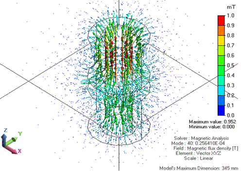
The distribution of the magnetic flux density at 0.25641e-5 [s] is shown below.
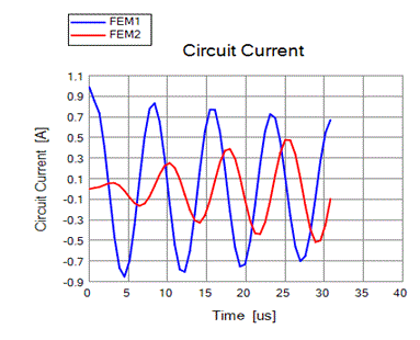
The circuit current waveforms are as follows.
The voltage source is a cosine wave, whereas the current of the primary coil (blue wave) is a sine wave over time.
It is observed that the currents of the primary coil and the secondary coil are shifted in phase.
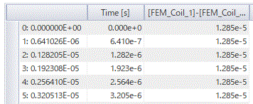
The result of inductance calculation is shown below.
Self-Inductance [H]
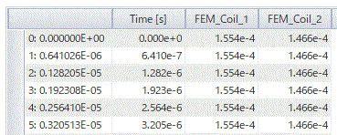
Mutual inductance [H]