|
Home / Examples / Magnetic Analysis (Luvens, Transient Analysis) / Example 15: Propulsion by Linear Motor
Example 15: Propulsion by Linear Motor
General
-
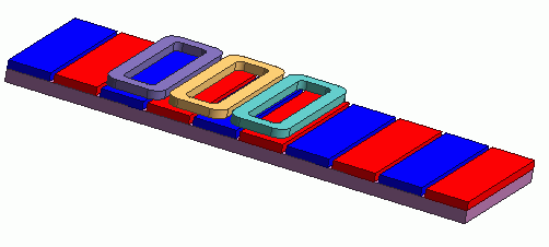
The propulsion by a coreless linear motor is analyzed.
-
The propulsion at a specified constant speed is solved.
-
The propulsion and the magnetic flux density distribution are solved.
-
The analysis is coupled with the external circuit.
-
Unless specified in the list below, the default conditions are applied.
-
Obtain this session's project file. (Right-click and choose 'Save link as')
-
Results will vary depending on Femtet version and the PC environment.
Analysis Conditions
|
Item |
Settings |
|
Analysis Space |
3D |
|
Unit |
mm |
|
Solver |
Magnetic Analysis [Luvens] |
|
Analysis Type |
Transient Analysis |
|
Analysis Options |
Select External Circuit Coupling. Select Translational Machinery. |
The Translational Machinery tab is set as follows.
|
Tab |
Setting Item |
Settings |
|
Translational Machinery |
Translational Move |
Moving Speed: 1.32 [m/s] |
|
Number of Sliding Mesh Divisions |
Division Size in Traveling Direction: 1.5 [mm] Traveling Quantity per Step: 1 [mesh] Number of Sliding Mesh Layers: 3 |
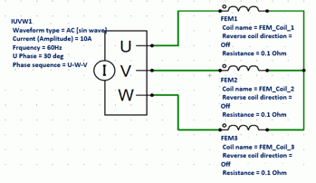
External circuit is as follows.
3-phase AC of 60 Hz and 10 A is applied.
Set the Mesh Tab as follows.
|
Tab |
Setting Item |
Settings |
|
Mesh |
Meshing Setup |
Set the general mesh size automatically: Deselect General Mesh Size: 1.5 [mm] |
|
Automatic Air Domain Creation |
Select Create air domain automatically Air Domain Scale: 2.0 |
The Transient Analysis tab is set up as follows.
The number of calculation steps is 10, the division size in the traveling direction is 1.5 [mm], and traveling quantity per step is 1 [mesh]. The mover’s travel distance up to 10*1.5*1=15 [mm] is analyzed.
-
As the input power is specified by current, the coil current is in the steady state from the beginning. The torque is also in the steady state.
|
Tab |
Setting Item |
Settings |
|||||
|
Transient analysis |
Timestep |
Automatic |
|||||
|
Table |
|
Model
The movers of 3-phase coils are placed in the center. The stators of magnets and yokes are placed on the sides of movers.
Side View
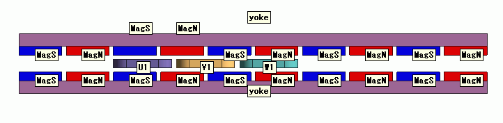
One End of the Model
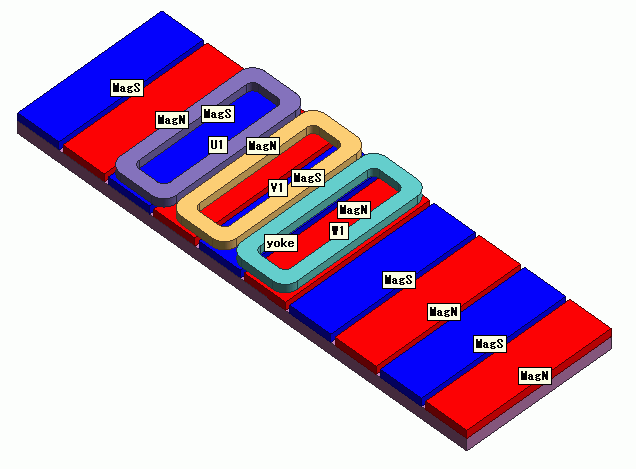
Body Attributes and Materials
|
Body Attribute Name |
Material Name |
|
MagN |
000_Neodymium_magnet * |
|
MagS |
000_Neodymium_magnet * |
|
Yoke |
Yoke |
|
U1 |
008_Cu * |
|
V1 |
008_Cu * |
|
W1 |
008_Cu * |
* Available from the material DB
The body attribute is set up as follows.
|
Body Attribute Name |
Tab |
Settings |
|
MagN |
Direction |
Vector: X=0, Y=0, Z=1 |
|
Stator/Rotor/Air |
Stator |
|
|
MagS |
Direction |
Vector: X=0, Y=0, Z=-1 |
|
Stator/Rotor/Air |
Stator |
|
|
Yoke |
Stator/Rotor/Air |
Stator |
|
U1 |
Current |
Waveform: External Circuit Coupling Coil Name on the Circuit: FEM_Coil_1 Turns: 20 [Turns] Direction: Loop Coil/Magnetic Field Direction Magnetic Field Vector: 0, 0, 1 |
|
Stator/Rotor/Air |
Mover |
|
|
V1 |
Current |
Waveform: External Circuit Coupling Coil Name on the Circuit: FEM_Coil_2 Turns: 20 [Turns] Direction: Loop Coil/Magnetic Field Direction Magnetic Field Vector: 0, 0, 1 |
|
Stator/Rotor/Air |
Mover |
|
|
W1 |
Current |
Waveform: External Circuit Coupling Coil Name on the Circuit: FEM_Coil_3 Turns: 20 [Turns] Direction: Loop Coil/Magnetic Field Direction Magnetic Field Vector: 0, 0, 1 |
|
Stator/Rotor/Air |
Mover |
The material properties are set as follows.
|
Material Name |
Tab |
Properties |
|
Yoke |
Permeability |
Material Type: Soft Magnetic Material |
|
Magnet |
Relative Permeability 3000 |
Boundary Condition
None
Results
The distribution of the magnetic flux density at a travel distance of 15 mm (10 calculation steps) is shown below.
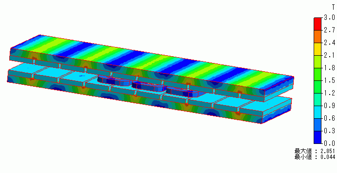
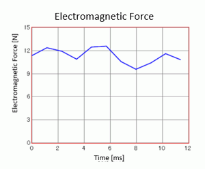
The diagram below shows time-propulsion characteristics. It is output to [mover/ X component] of [Electromagnetic force [N]] in the result table.
The propulsion of about 11 [N] is obtained.