|
Home / Examples / Magnetic Analysis (Luvens, Transient Analysis) / Example 6: Torque Analysis of Outer Rotor Motor
Example 6: Torque Analysis of Outer Rotor Motor
General
-
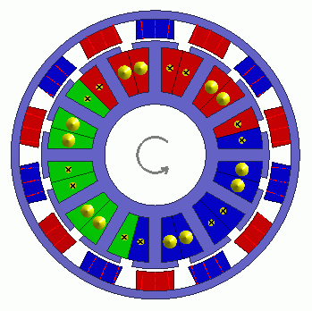
Torque characteristics of an outer rotor motor for a drone is analyzed when electricity is applied.
The model is a permanent magnet synchronous motor with magnets arragned on the outer rotor. -
The analysis is coupled with the external circuit.
-
The torque and the magnetic flux density are solved.
-
Unless specified in the list below, the default conditions will be applied.
-
Obtain this session's project file. (Right-click and choose 'Save link as')
-
Results will vary depending on Femtet version and the PC environment.
Analysis Conditions
|
Item |
Settings |
|
Analysis Space |
2D |
|
Thickness in Depth Direction |
6 [mm] |
|
Unit |
mm |
|
Solver |
Magnetic Analysis [Luvens] |
|
Analysis Type |
Transient Analysis |
|
Options |
Select External Circuit Coupling. Select Rotating Machinery. |
The Rotating Machinery tab is set as follows.
|
Tab |
Setting Item |
Settings |
|
Rotating Machinery |
Rotational Movement |
Select Constant Velocity Number of Rotations: 7200 [r/min] Rotor’s Initial Rotation Position: 0 [deg] |
|
Number of Sliding Mesh Divisions |
Circumferential Division Angle: 1.0 [deg] Rotational Quantity per Step: 1 [mesh] Number of Sliding Mesh Layers: 3 |
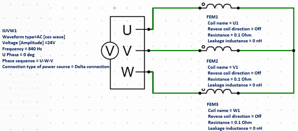
External circuit is as follows.
3-phase AC voltage of 840 Hz is applied.
Set the Mesh Tab as follows.
|
Tab |
Setting Item |
Settings |
|
Mesh |
Meshing Setup |
Automatically set the general mesh size: Deselect General Mesh Size: 0.4 [mm] |
|
Air Domain Creation |
Select Create air domain automatically Air Domain Scale: 1.2 |
The Transient Analysis tab is set up as follows.
The umber of calculation steps is 180, circumferential division angle is 1.0 [deg], and rotational quantity per step is 1 [mesh]. The rotation up to 180 deg (=180*1.0*1) is analyzed.
|
Tab |
Setting Item |
Settings |
|||||
|
Transient Analysis |
Timestep |
Automatic |
|||||
|
Table |
|
Graphical Objects
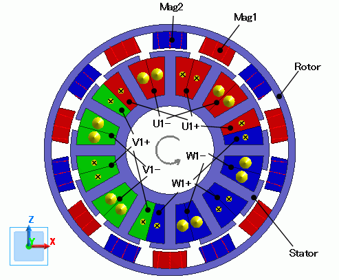
A stator core and coils are placed in the center. A rotor core and magnets are placed around them.
The motor has 14 poles.
This is a 2D model analysis.
[Create air domain automatically] is selected.
Body Attributes and Materials
|
Body Number/Type |
Body Attribute Name |
Material Name |
|
4/Sheet |
Mag1 |
mag |
|
6/Sheet |
Mag1 |
mag |
|
8/Sheet |
Mag1 |
mag |
|
10/Sheet |
Mag1 |
mag |
|
12/Sheet |
Mag1 |
mag |
|
14/Sheet |
Mag1 |
mag |
|
16/Sheet |
Mag1 |
mag |
|
5/Sheet |
Mag2 |
mag |
|
7/Sheet |
Mag2 |
mag |
|
9/Sheet |
Mag2 |
mag |
|
11/Sheet |
Mag2 |
mag |
|
13/Sheet |
Mag2 |
mag |
|
15/Sheet |
Mag2 |
mag |
|
17/Sheet |
Mag2 |
mag |
|
0/Sheet |
Rotor |
core |
|
37/Sheet |
Stator |
core |
|
40/Sheet |
U1- |
Cu |
|
42/Sheet |
U1- |
Cu |
|
51/Sheet |
U1- |
Cu |
|
53/Sheet |
U1- |
Cu |
|
39/Sheet |
U1+ |
Cu |
|
41/Sheet |
U1+ |
Cu |
|
43/Sheet |
U1+ |
Cu |
|
52/Sheet |
U1+ |
Cu |
|
44/Sheet |
V1- |
Cu |
|
46/Sheet |
V1- |
Cu |
|
55/Sheet |
V1- |
Cu |
|
57/Sheet |
V1- |
Cu |
|
45/Sheet |
V1+ |
Cu |
|
47/Sheet |
V1+ |
Cu |
|
54/Sheet |
V1+ |
Cu |
|
56/Sheet |
V1+ |
Cu |
|
48/Sheet |
W1- |
Cu |
|
50/Sheet |
W1- |
Cu |
|
59/Sheet |
W1- |
Cu |
|
61/Sheet |
W1- |
Cu |
|
38/Sheet |
W1+ |
Cu |
|
49/Sheet |
W1+ |
Cu |
|
58/Sheet |
W1+ |
Cu |
|
60/Sheet |
W1+ |
Cu |
The body attribute is set up as follows.
|
Body Attribute Name |
Tab |
Settings |
|
Mag1 |
Direction |
Direction Type: Centripetal Direction Direction: Outward |
|
Stator/Rotor/Air |
Rotor |
|
|
Mag2 |
Direction |
Direction Type: Centripetal direction Inward |
|
Stator/Rotor/Air |
Rotor |
|
|
Rotor |
Stator/Rotor/Air |
Rotor |
|
Stator |
Stator/Rotor/Air |
Stator |
|
U1- |
Current |
Waveform: External Circuit Coupling Coil Name on the Circuit: U1 Turns: 35 [Turns] Direction: - Y Direction |
|
Stator/Rotor/Air |
Stator |
|
|
U1+ |
Current |
Waveform: External Circuit Coupling Coil name on the circuit: U1 Turns: 35[Turns] Direction: +Y Direction |
|
Stator/Rotor/Air |
Stator |
|
|
V1- |
Current |
Waveform: External Circuit Coupling Coil Name on the Circuit: V1 Turns: 35 [Turns] Direction: - Y Direction |
|
Stator/Rotor/Air |
Stator |
|
|
V1+ |
Current |
Waveform: External Circuit Coupling Coil name on the circuit: V1 Turns: 35 [Turns] Direction: +Y Direction |
|
Stator/Rotor/Air |
Stator |
|
|
W1- |
Current |
Waveform: External Circuit Coupling Coil Name on the Circuit: W1 Turns: 35 [Turns] Direction: - Y Direction |
|
Stator/Rotor/Air |
Stator |
|
|
W1+ |
Current |
Waveform: External Circuit Coupling Coil name on the circuit: W1 Turns: 35 [Turns] Direction: +Y Direction |
|
Stator/Rotor/Air |
Stator |
The material properties are set as follows.
|
Material Name |
Tab |
Properties |
||||||||||||||||||||||
|
Cu |
Conductivity |
Conductivity Type: Conductor Conductivity: 5.977x10⁷ [S/m] |
||||||||||||||||||||||
|
mag |
Permeability |
Material Type: Permanent Magnet |
||||||||||||||||||||||
|
Magnet |
Magnetization Characteristic Type: Linear Magnetization Strength: 1.25 Relative Permeability: 1.05 |
|||||||||||||||||||||||
|
core |
Permeability |
Magnetization Characteristic Type: Select B-H curve
B-H Curve Table
|
Results
The distribution of the magnetic flux density at the rotation angle of 0 [deg] is shown below.
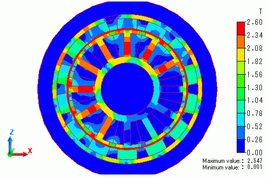
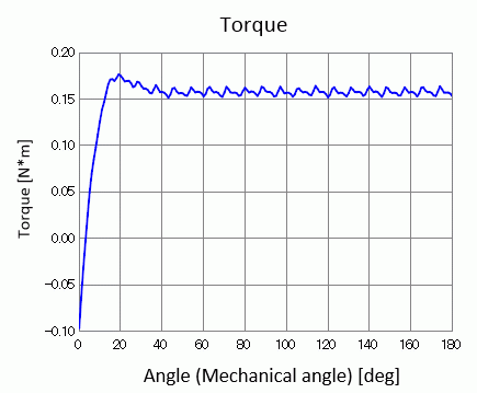
The torque waveform is shown as below. It is output to "Torque [N*m]" of the result table.
Transient state becomes steady at around 50 [deg].