


|
Home / Examples / Acoustic Analysis [Mach] / Example 17: Incident Plane Wave
Example 17: Incident Plane Wave
General
-
Apply plane waves.
-
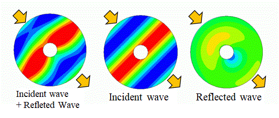
Then, reflected waves are generated due to a hole in the model. The incident and reflected waves are displayed separately.
-
Obtain this session's project file. (Right-click and choose 'Save link as')
Analysis Space
|
Item |
Settings |
|
Analysis Space |
2D |
|
Model Unit |
m |
|
Thickness in Depth Direction |
1 [m] |
Analysis Conditions
|
Item |
Settings |
|
Solver |
Acoustic Analysis |
|
Analysis Type |
Harmonic Analysis |
|
Options |
Incident Wave |
|
Tab |
Item |
Settings |
|
Harmonic Analysis |
Frequency |
Single Frequency 0.5 [kHz] |
|
Sweep Setting |
Discrete Sweep |
|
|
Options |
Select [Enable each port's individual weight setting for the field display]. |
|
|
|
|
|
|
Incident Wave (plane wave) |
Propagation Direction |
(1, -1, 0) |
|
Pressure (Sound Pressure) |
1 [Pa] Select [Sound Pressure [Pa]]. |
Model
A hole is provided in the body of air. The hole does not need any setting. It is treated as a rigid wall, which has been set for the outer boundary condition.
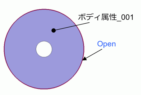
Body Attribute and Material Property Setting
|
Body Number/Type |
Body Attribute Name |
Material Name |
|
Body2/Sheet Body |
Body_Attribute_001 |
000_Air * |
* Available from the material DB
Boundary Conditions
|
Boundary Condition Name/Topology |
Tab |
Boundary Condition Type |
Settings |
|
Open/Edge |
Acoustic |
Open Boundary |
|
|
Outer Boundary Condition |
Acoustic |
Rigid Wall |
|
Results
How to separate incident and reflected waves, shown at the top of this page, is explained below.
1. Display the gradation contour of the sound pressure [Pa] of the result fields.
2. Go to Graphics Setting to click it, and select [Field Superposition Setting] on the pull-down menu. The dialog box will appear (Fig. 1)
3. Select [Synthetic Wave] for the Plane Wave field type and click the OK button. The superposed result of incident and reflected waves is displayed. (Left side of Fig. 2)
4. Select [Incident Wave] for the Plane Wave field type and click the OK button. The incident wave is displayed. (Center of Fig. 2)
5. Select [Reflected Wave] for the Plane Wave field type and click the OK button. The reflected wave is displayed. (Right side of Fig. 2)
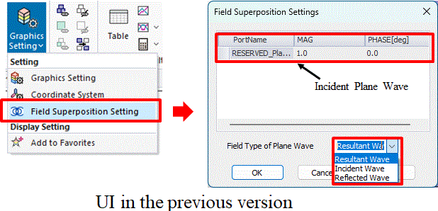
Fig. 1 Field Superposition Settings dialog box
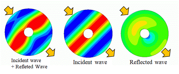
Fig. 2 Result Field Displays