|
Home / Examples / Acoustic Analysis [Mach] / Example 9: Better Accuracy of the Open Boundary
Example 9: Better Accuracy of the Open Boundary
General
-
The analysis domain other than the sphere is solved with the 2nd-order open boundary condition.
-
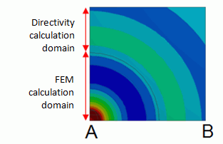
The analysis domain near the driving source is solved by FEM. The outside of the domain is solved using the directivity calculation method. As the 2nd-order absorbing open boundary is applicable only to the sphere, Femtet creates the sphere inside the analysis domain and the 2nd-order absorbing open boundary is applied thereto to perform analysis.
-
Obtain this session's project file. (Right-click and choose 'Save link as')
-
Results will vary depending on Femtet version and the PC environment.
Analysis Conditions
|
Item |
Settings |
|
Solver |
Acoustic Analysis (Mach) |
|
Analysis Space |
3D |
|
Analysis Type |
Harmonic Analysis |
|
Model unit |
mm |
Harmonic Analysis tab and Open Boundary tab are set as follows.
|
Tab |
Setting Item |
Settings |
|
Harmonic Analysis |
Frequency: Sweep Type |
Single Frequency |
|
Frequency: Sweep Values |
1 [kHz] |
|
|
Frequency Sweep |
Discrete Sweep |
|
|
Open Boundary |
Types |
Absorbing Boundary |
|
Order of Absorbing Boundary |
2nd-order |
|
|
Radius of the Open Boundary |
0.3 [m] |
-
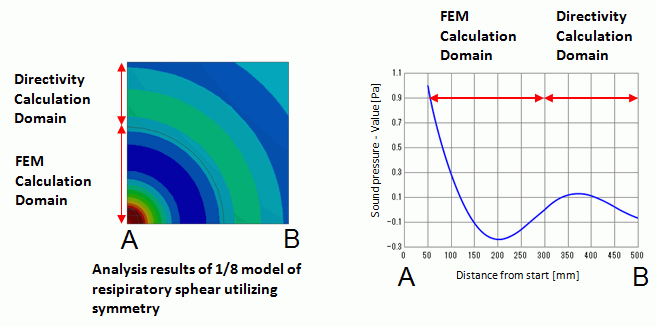
The inside of the radius of the open boundary is solved by FEM. The outside is solved by the directivity calculation.
Graphical Objects
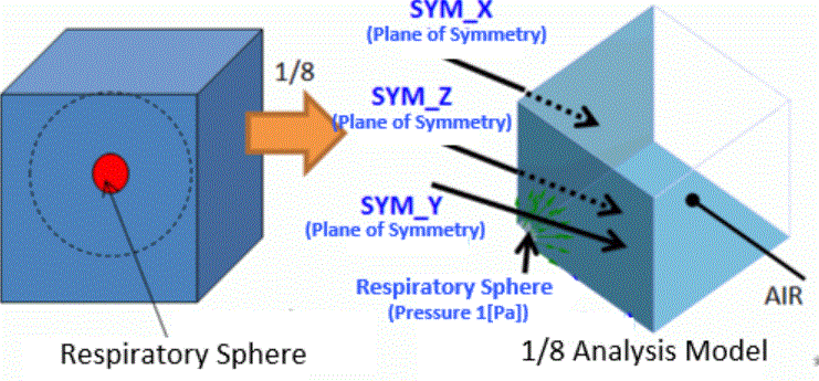
Default value (50) is used for the general mesh size. The left figure below is the analysis object. The area encircled by the dots is analyzed by FEM. The area includes the respiratory sphere as a sound source. By utilizing the symmetry of the analysis model, it is made to be 1/8 model
Body Attributes and Materials
|
Body Number/Type |
Body Attribute Name |
Material Name |
|
2/Solid |
AIR |
000_Air(*) |
* Available from the material DB
Boundary Conditions
|
Boundary Condition Name/Topology |
Tab |
Boundary Condition Type |
Setting |
|
SYM_X/Face |
Symmetry/Continuity |
Symmetry |
Reflective |
|
SYM_Y/Face |
Symmetry/Continuity |
Symmetry |
Reflective |
|
SYM_Z/Face |
Symmetry/Continuity |
Symmetry |
Reflective |
|
Respiratory sphere/Face |
Sound Wave |
Pressure |
1 [Pa] |
|
Outer Boundary Condition * |
Sound Wave |
Rigid Wall |
|
*Although the rigid wall is selected for the outer boundary condition, it does not function as the rigid wall because it is out of the domain for the finite element method.
Results
The sound pressure distribution is shown in the contour below left. The change of the sound pressure between A and B is shown in the graph below right.
To show the contour of the face including the respiratory sphere, [Full Model] is deselected. The division setting is changed from [Automatic] to [Number of Divisions] and 100 is set for the Number of Divisions.