


|
Home / Examples / Acoustic Analysis [Mach] / Example 14: Sound-absorbing Material (miki model)
Example 14: Sound-absorbing Material (miki model)
General
-
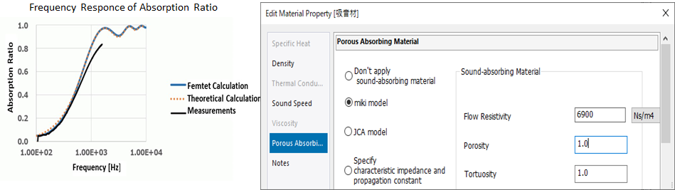
In Example 13, material properties of sound-absorbing materials are calculated using Excel, while, in this example, material properties can be calculated on the porous absorbing material tab.
-
The model of this example is created referring to the website of Architectural Institute of Japan (AIJ).
-
The characteristics of a sound-absorbing material is analyzed with the miki model (see the example 13 on the Femtet help menu).
-
Obtain this session's project file. (Right-click and choose 'Save link as')
-
Results will vary depending on Femtet version and the PC environment.
Analysis Space
|
Item |
Settings |
|
Analysis Space |
2D Thickness in Depth Direction: 1 [mm] |
|
Model Unit |
mm |
Analysis Conditions
|
Item |
Settings |
|
Solver |
Acoustic Analysis [Mach] |
|
Analysis Type |
Harmonic Analysis |
|
Options |
Select [Calculate loss]. |
The harmonic analysis tab and mesh tab are set as follows.
|
Tab |
Setting Item |
Settings |
|
Mesh |
General Mesh Size: |
1 |
|
Harmonic Analysis |
Frequency |
Minimum: 100 [Hz] Maximum: 10000 [Hz] |
|
Interval |
Select [Log Step] Number of Divisions: 100 |
|
|
Frequency Sweep |
Select Discrete Sweep. |
Model
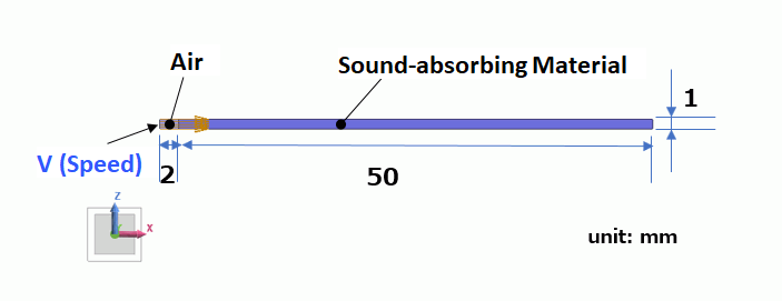
Create a rectangular sheet body, 50 x 1 [mm], and assign sound-absorbing material to the body. To its left, create a sheet body of air, 2 x 1 [mm].
Set the speed boundary condition, v, to the edge at the left end of the air domain. The other edges have no boundary conditions, resulting in outer boundary conditions of the rigid wall.
Body Attributes and Materials
|
Body Number/Type |
Body Attribute Name |
Material Name |
|
0/Solid |
Sound-absorbing Material |
Sound-absorbing Material |
|
1/Solid |
AIR |
000_Air |
|
Material Name |
Tab |
Settings |
|
Sound-absorbing Material |
Sound Speed |
Real Part: 340 [m/s] |
|
Density |
1.144 [kg/m3] |
|
| Porous Absorbing Material | Select [miki model] Flow Resistivity: 6900 [Ns/m4] Tortuosity: 1 Porosity: 1 |
Boundary Condition
|
Boundary Condition Name/Topology |
Tab |
Boundary Condition Type |
Settings |
|
v/Edge |
Sound Wave |
Speed |
1.0 [m/s] Select [Specify the incident wave] |
|
Outer Boundary Condition |
Acoustic |
Rigid Wall |
|
Results
1. Frequency Response of Radiation Impedance
In the result table, go to the [Detailed Radiation Impedance] tab, select [Show all results summary], and click the [Graph] button. The frequency response graph will appear.
The figure is the same as in Example 13: Sound-absorbing Material (Table Input).
See Example 13 for calculating the frequency response of absorbing ratio.
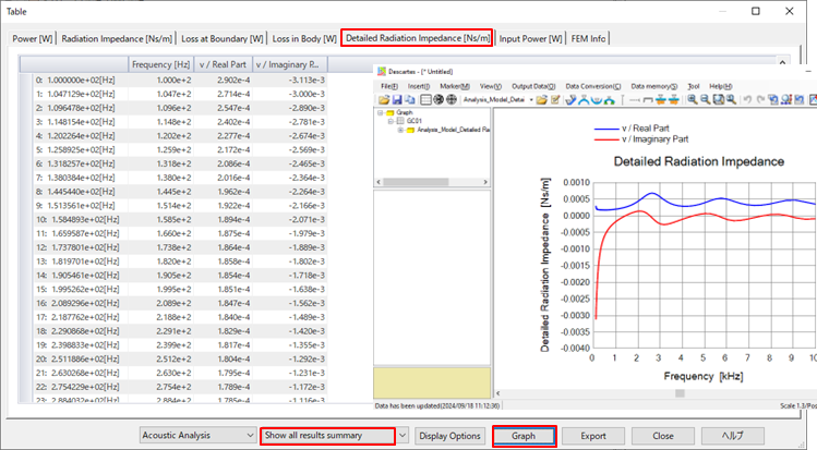
Fig. 1 Frequency Response of Radiation Impedance (Table and Graph)