


|
Home / Examples / Piezoelectric Analysis [Rayleigh] / Example 3: Resonant Analysis
Example 3: Resonant Analysis
General
-
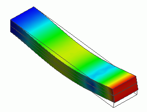
The model is a bar with two reversely polarized piezoelectric plates stuck together. The model is studied in the resonant analysis.
-
The device's displacement and the resonant frequencies are solved.
-
Unless specified in the list below, the default conditions will be applied.
-
Obtain this session's project file. (Right-click and choose 'Save link as')
-
Results will vary depending on Femtet version and the PC environment.
Analysis Space
|
Item |
Settings |
|
Analysis Space |
3D |
|
Model Unit |
mm |
Analysis Conditions
|
Item |
Settings |
|
Solver |
Piezoelectric Analysis [Rayleigh] |
|
Analysis Type |
Resonant Analysis |
|
Options |
N/A |
The resonant analysis tab is set up as follows.
|
Tab |
Setting Item |
Settings |
|
Resonant analysis |
Number of Modes |
3 |
Model
Two solid bodies are created. They are named "upper" and "lower", and reversely polarized.
One end is mechanically fixed. The electric potentials of top and bottom faces are 10 [V] and 0 [V], respectively. The same model as the example 1.
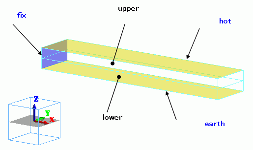
Body Attributes and Materials
|
Body Number/Type |
Body Attribute Name |
Material Name |
|
0/Solid |
upper |
000_P-4 * |
|
1/Solid |
lower |
000_P-4 * |
* Available from the material DB
The polarizations are set as follows.
|
Body Attribute Name |
Tab |
Settings |
|
upper |
Direction |
Vector Specified: Vector: X=Y=0.0, Z=1.0 |
|
lower |
Direction |
Vector Specified: Vector: X=Y=0.0, Z=-1.0 |
Boundary Conditions
|
Boundary Condition Name/Topology |
Tab |
Boundary Condition Type |
Settings |
|
fix/Face |
Mechanical |
Displacement |
Select all UX, UY, and UZ. UX=0, UY=0, UZ=0 |
|
earth/Face |
Electric |
Electric Wall |
Electric Potential Specified: Electric Potential 0 [V] |
|
hot/Face |
Electric |
Electric Wall |
Electric Potential Specified: Electric Potential 10 [V] |
Results
To see the calculation results, go to the [Results] tab

and click [Show Numerical Summary Table]  .
.
The table below shows the resonant frequencies.
Other characteristics can be seen on other tabs.
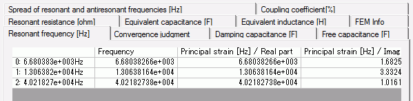
The displacement diagram of Mode[0] is shown below.
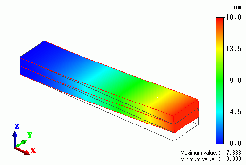
The displacement diagram of Mode[1] is shown below.
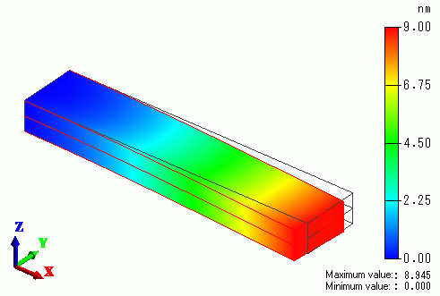
The vibration direction is different from Mode[0]
The displacement diagram of Mode[2] is shown below.
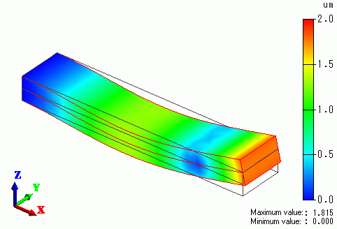
The vibration direction is the same as Mode[0], but the number of nodes are different.