


|
Home / Examples / Coupled Analysis / Thermal-Stress Analysis [Watt/Galileo] / Example 3: Deformation due to the Temperature Gradient #3 - Multiple Materials
Example 3: Deformation due to the Temperature Gradient #3 - Multiple Materials
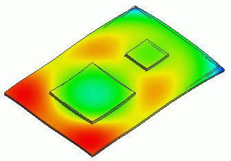
General
-
A heating chip is placed on a substrate. Under the condition of heating by chip and cooling by natural convection,
the temperature distribution is calculated the same as in Example 10, resulting in thermal expansion. Using the results, the stress is calculated in the stress analysis.
-
The temperature distribution is calculated using the thermal analysis [Watt].
The result is forwarded to the stress analysis [Galileo] as a thermal load corresponding to the reached temperature.
-
The deformation, the displacement and the stress are solved.
-
Unless specified in the list below, the default conditions will be applied.
-
Obtain this session's project file. (Right-click and choose 'Save link as')
-
Results will vary depending on Femtet version and the PC environment.
Analysis Space
|
Item |
Settings |
|
Analysis Space |
3D |
|
Model Unit |
mm |
Analysis Conditions
Select Thermal analysis and Stress analysis.
|
Item |
Settings |
|
Solver |
Thermal Analysis [Watt] |
|
Thermal-Analysis Type |
Steady-State Analysis |
|
Options |
N/A * |
* [Thermal Load] is selected by default for the thermal-stress coupled analysis.
The Step/Thermal Load tab is set as follows.
|
Tab |
Setting Item |
Settings |
|
Step/Thermal Load * |
Reference Temperature |
25 [deg] |
* The reached temperatures come from the thermal analysis.
Model
The same as Example 10 of thermal analysis.
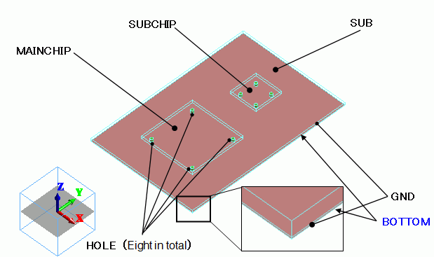
Body Attributes and Materials
|
Body Number/Type |
Body Attribute Name |
Material Name |
|
0/Solid |
SUB |
006_Glass_epoxy * |
|
1/Solid |
GND |
008_Cu * |
|
2/Solid |
MAINCHIP |
001_Alumina * |
|
3/Solid |
SUBCHIP |
001_Alumina * |
|
4/Solid |
HOLE |
008_Cu * |
|
5/Solid |
HOLE |
008_Cu * |
|
6/Solid |
HOLE |
008_Cu * |
|
7/Solid |
HOLE |
008_Cu * |
|
8/Solid |
HOLE |
008_Cu * |
|
9/Solid |
HOLE |
008_Cu * |
|
10/Solid |
HOLE |
008_Cu * |
|
11/Solid |
HOLE |
008_Cu * |
* Available from the material DB
The heat quantities of MAINCHIP and SUBCHIP are set up as follows.
|
Body Attribute Name |
Tab |
Settings |
|
MAINCHIP |
Heat Quantity |
0.2 [W] |
|
SUBCHIP |
Heat Quantity |
0.1 [W] |
Boundary Conditions
The coefficient of heat transfer for the natural convection is set on the bottom face of GND as follows:
The radiation from the top and the sides is omitted.
|
Boundary Condition Name/Topology |
Tab |
Boundary Condition Type |
Settings |
|
Bottom/Face |
Thermal |
Heat Transfer/Convection |
Natural convection *: 1.39 [W/m2/deg5/4] Room temperature: 25[deg] |
* The coefficient for the natural convection is calculated as follows.
2.51×C×(1/L)^(1/4) = 1.39 [W/m2/deg5/4]
where
C = 0.26
Size of the substrate : 0.06x0.04
L (Typical Length) = (0.06 x 0.04 x 2) / (0.06 + 0.04) = 0.048
Results
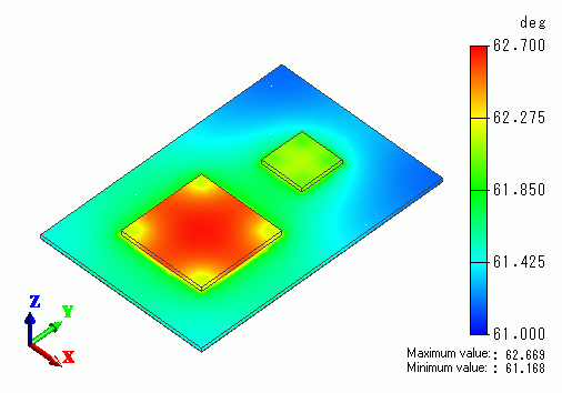
The temperature distribution as a result of Watt is shown below.
The next figure shows the vectors of displacement as a result of Galileo following Watt.
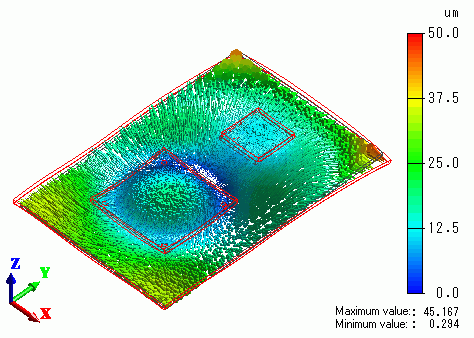
The substrate corners which shows the low temperature are bent downward.