


|
Home / Examples / Thermal Analysis [Watt] / Example 24: Thermal Analysis Using Results (Heat Density) Imported from Magnetic Field Harmonic Analysis
Example 24: Thermal Analysis Using Results (Heat Density) Imported from Electric-Harmonic Analysis
General
-
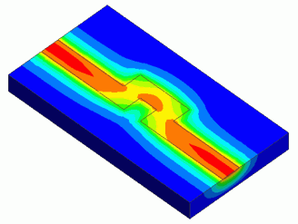
The loss density imported from the electric-harmonic analysis is used for the thermal analysis.
-
The temperature distribution and the heat flux vectors are solved.
-
Unless specified in the list below, the default conditions will be applied.
-
Obtain this session's project file. (Right-click and choose 'Save link as')
-
Results will vary depending on Femtet version and the PC environment.
Analysis Conditions
|
Item |
Setting |
|
Solver |
Thermal Analysis [Watt] |
|
Analysis Space |
3D |
|
Analysis Type |
Steady-state Analysis |
|
Unit |
mm |
|
Results Import |
Heat Density |
Model
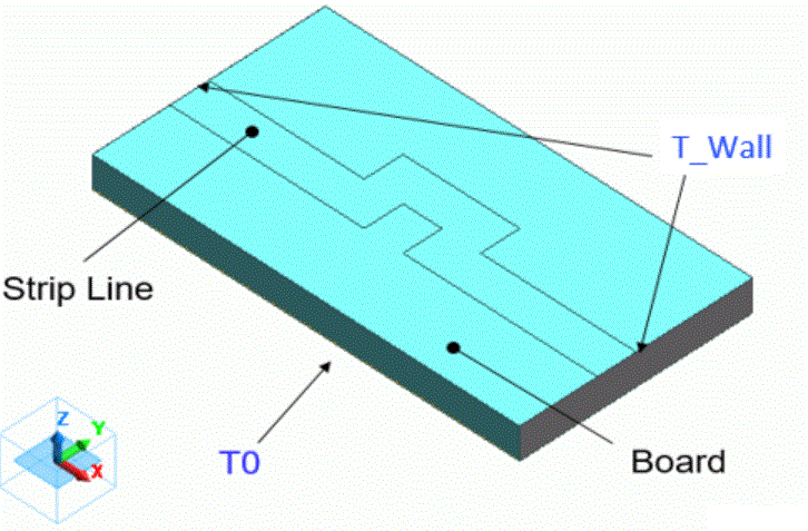
The board is a rectangular solid body.
The strip line is a sheet body created on the surface of the board.
Body Attributes and Materials
|
Body Number/Type |
Body Attribute Name |
Material Name |
|
0/Solid |
VOL1 |
001_Alumina * |
|
6/Sheet |
VOL2 |
008_Cu (*) |
* Available from the material DB
The conductive strip line is a sheet body. Its thickness must be defined.
The values of current and heat quantity will vary depending on the thickness.
|
Body Attribute Name |
Thickness/Width |
Analysis Domain |
|
StripLine |
Thickness of Sheet Body : 0.1mm |
|
Boundary Condition
-
The temperature of the bottom face of the substrate is set to 25 [deg] by the boundary condition of T0.
-
The faces where the strip line ends are set with the [Adiabatic] boundary condition, T_Wall.
Accordingly, the outer boundary condition, as stated below, will not be applied to the faces. -
The heat transfer to the ambient is defined by the outer boundary condition.
|
Boundary Condition Name/Topology |
Tab |
Boundary Condition Type |
Setting |
|
T_Wall/Face |
Thermal |
Adiabatic |
|
|
T0/Face |
Thermal |
Temperature |
25 [deg] |
|
Outer Boundary Condition * |
Thermal |
Heat Transfer/Convection |
Coefficient of Heat Transfer: 10 [W/m2/deg] Ambient Temperature: 25 [deg] |
Results
First, run the electric analysis in the project. The loss density diagram is shown below.
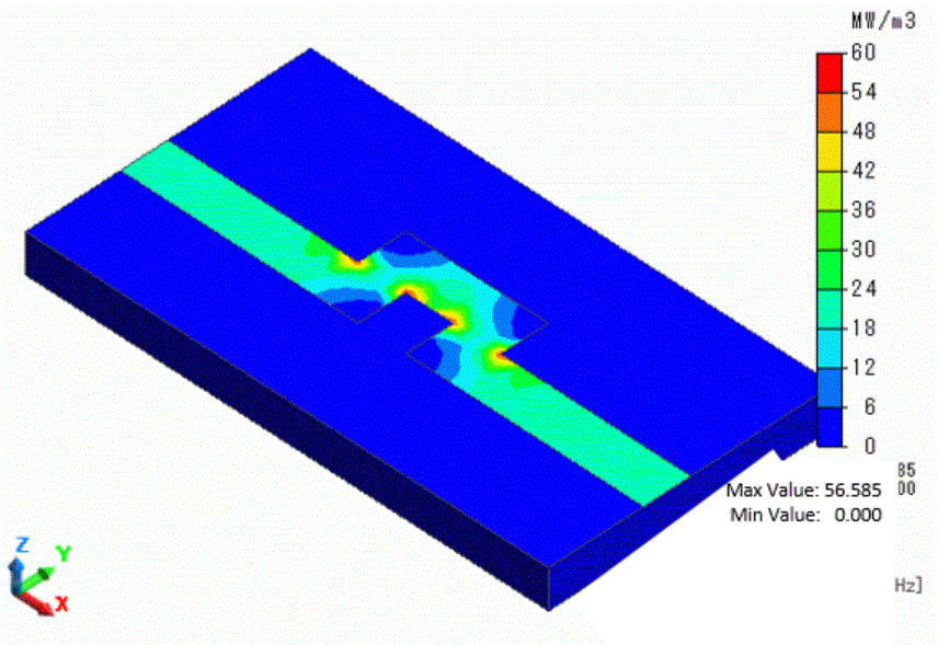
You can see the current density is distributed around the bending area of the strip.
Next, run the thermal analysis in the project. The diagram below shows the temperature distribution.
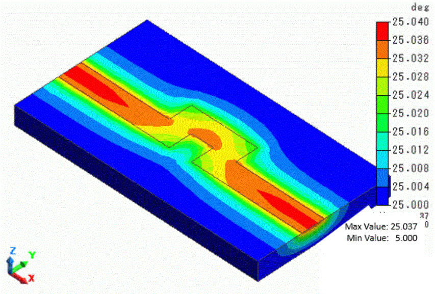
Temperature rise due to heat generation occurs along the strip line, and the heat is transmitted to the alumina substrate.