Home / Modeling / Drawing Process / How to Create Primitives / Solid Bodies / Helical/Spiral Prism
Helical/Spiral Prism
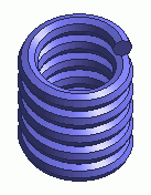
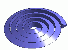
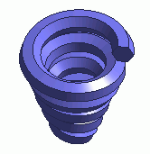
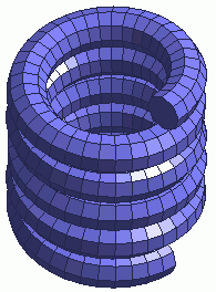
Pattern 1 (Helix) Pattern 2 (Spiral 1) Pattern 3 (Spiral 2)
Create a helical/spiral prism (solid body).
Procedure
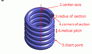
Pattern 1 (Helix)
-
On the [Model] tab, go to  and click ▼ at the bottom of [Solid Body] and click ▼ at the bottom of [Solid Body]  . Select [Helical/Spiral Prism] . Select [Helical/Spiral Prism]  on the submenu. on the submenu.
-
Click and set the center-axis point on the .
(Alternatively enter the coordinates in the , and click  .) .)
-
Enter the radius of cross section in the parameter input dialog box , and click .
-
Enter the number of corners of cross section in the parameter input dialog box, and click .
-
Click the position to set the startpoint on the modeling window.
(Alternatively enter the coordinates in the parameter input dialog box, and click .)
-
Enter the helical pitch in the parameter input dialog box, and click .
-
Enter the spiral pitch (0 in this case)in the parameter input dialog box, and click .
-
Enter the number of turns in the parameter input dialog box, and click  . .
-
Right click to exit.
|
|
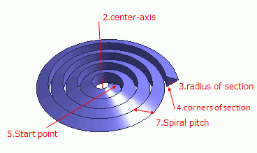
Pattern 2 (spiral)
-
On the [Model] tab, go to and click ▼ at the bottom of [Solid Body] . Select [Helical/Spiral Prism] on the submenu.
-
Click and set the center-axis point on the .
(Alternatively enter the coordinates in the , and click .)
-
Enter the radius of cross section in the parameter input dialog box , and click .
-
Enter the number of corners of cross section in the parameter input dialog box, and click .
-
Click the position to set the startpoint on the modeling window.
(Alternatively enter the coordinates in the parameter input dialog box, and click .)
-
Enter the helical pitch: 0 in the parameter input dialog box, and click .
-
Enter the spiral pitch in the parameter input dialog box, and click .
-
Enter the number of turns in the parameter input dialog box, and click .
-
Right click to exit.
|
|
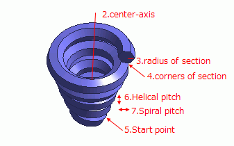
Pattern 3 (Spiral 2)
-
On the [Model] tab , click ▼ at the bottom of [Solid Body] . Select [Helical/Spiral Prism] on the submenu.
-
Click and set the center-axis point on the .
(Alternatively enter the coordinates in the , and click .)
-
Enter the radius of cross section in the parameter input dialog box , and click .
-
Enter the number of corners of cross section in the parameter input dialog box, and click .
-
Click the position to set the startpoint on the modeling window.
(Alternatively enter the coordinates in the parameter input dialog box, and click .)
-
Enter the helical pitch in the parameter input dialog box, and click .
-
Enter the spiral pitch in the parameter input dialog box, and click .
-
Enter the number of turns in the parameter input dialog box, and click .
-
Right click to exit.
|
|
Flattening Sides
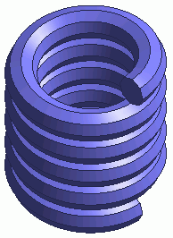
The side of helical/spiral prism is always curved face.
Mesh creation sometimes fails due to the curved face of the helical/spiral prism.
In such case, by selecting [Flatten Sides],
the failure might be avoided.
Please note, however, that by selecting [Flatten Sides],
face topologies will increase and might incur the following problems.
|
[Flatten Sides] deselected [Flatten Sides] selected
|


