Chamfer the selected edge topologies.
There are 3 methods to chamfer.
Method 1 / Chamfer (isosceles)
-
On the [Model] tab, go to
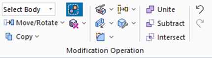
and click [Select Edge] on the drop-down list at  . .
|
|
-
On the [Model] tab, go to
,
and click ▼ at the side of [Fillet]  . Select [Chamfer [Isosceles]] . Select [Chamfer [Isosceles]]  on the submenu. on the submenu.
(Alternatively, right click the mouse. On the appearing menu, select [Deform]-[Chamfer]-[Chamfer [isosceles]])
|
|
-
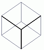
Select the edge topologies to chamfer.
|
|
-
Click  in the parameter input dialog box. in the parameter input dialog box.
|

|
|
-
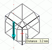
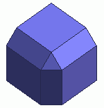
Enter the distance in the , and click  . .
(Alternatively click and set the distance on the .)
|
|
|
|
Method 2 / Chamfer (scalene)
-
On the [Model] tab
click [Select Edge] on the drop-down list at .
|
|
-
On the [Model] tab, go to
,
and click ▼ at the side of [Fillet] . Select [Chamfer [Scalene]]  on the submenu. on the submenu.
(Alternatively, right click the mouse. On the appearing menu, select [Modify]-[Chamfer]-[Chamfer [scalene]])
|
|
-
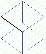
Select the edge topologies to chamfer.
|
|
-
Click in the parameter input dialog box.
|

|
-
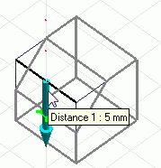
Enter the 1st distance in the , and click .
(Alternatively, click and set the distance on the .)
-
There will be a preview when the distance is entered.
-
The side to enter the distance will be indicated by an arrow.
|
|
-
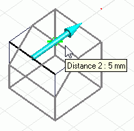
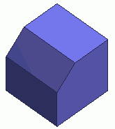
Enter the 2nd distance in the , and click .
(Alternatively, click and set the distance on the .)
-
The side to enter the distance will be indicated by an arrow.
|
|
|
|
Method 3
-
On the [Model] tab
click [Select Edge] on the drop-down list at .
|
|
-
On the [Model] tab, go to
,
and click ▼ at the side of [Fillet] . Select [Chamfer [Angle]]  on the submenu. on the submenu.
(Alternatively, right click the mouse. On the appearing menu, select [Chamfer]-[Chamfer [angle]])
|
|
-
Select the edge topologies to chamfer.
|
|
-
Click in the parameter input dialog box.
|
|
-
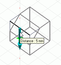
Enter the distance in the , and click .
(Alternatively, click and set the distance on the .)
-
There will be a preview when the distance is entered.
-
The side to enter the distance will be indicated by an arrow.
|
|
-
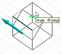
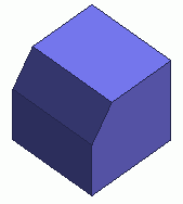
Enter the angle in the , and click .
(Alternatively, click and set the angle on the .)
-
The unit of angle is [ ° ]
|
|
|
|
|


