|
Home / How to Set Analysis Condition / List of Analysis Condition Tabs / MATLAB/Simulink Tab
MATLAB/Simulink Tab
In the magnetic transient analysis, the setting is done on this tab for the integrated analysis with MATLAB/Simulink motor drive analysis.
See here for the integration with MATLAB/Simulink motor drive analysis.
This tab setting is not required unless you perform the integrated analysis with MATLAB/Simulink motor drive analysis.
This tab becomes active if the Magnetic Analysis tab is set as follow.
Analysis type: [Transient analysis (Luvens)]
Options (Luvens): [External Circuit Coupling] and [Rotating Machinery] are selected.
It is in the [Analysis Condition Setting] dialog box. See also [How to Set Analysis Condition].
|
Setting Item |
Notes |
|
Integration with MATLAB |
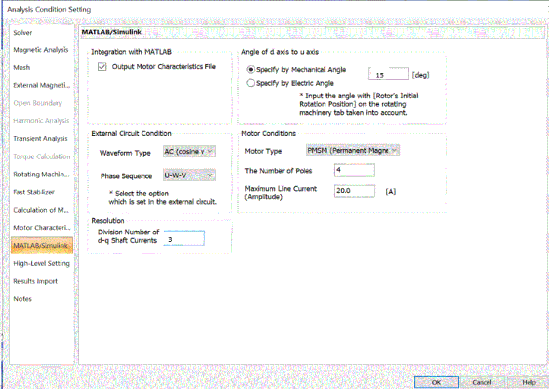
Output Motor Characteristics File Creates a motor characteristics file for the MATLAB/Simulink motor drive analysis.
|
|
External Circuit Condition |
Waveform Type Specifies the waveform for the external circuit.
Phase Sequence Specifies the phase sequence for the external circuit.
|
|
Resolution |
Number of Divisions of d-q Shaft Currents Specifies the number of divisions of current for calculation. The larger number of divisions increases the calculation accuracy but takes longer time.
|
|
Angle of d-axis to u-axis |
Sets the angle of d-axis to u-axis at the initial time. With reference to the u-axis, if the d-axis is advanced, set the positive value. If it is behind, set the negative value.
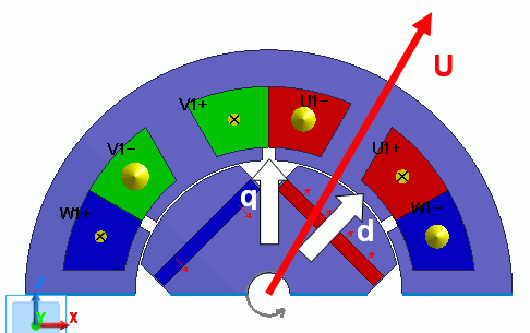
Definition of Each Axisd-axis: Center axis of permanent magnet (magnetic flux direction generated by magnetic pole) q-axis: Axis between permanent magnets (axis magnetically crossing the d axis at the right angle) u-axis: Magnetic flux direction generated by U-phase coil ExampleIn the diagram below, the mechanical angle of the d-axis to the u-axis is -15[deg].
|
|
Motor Conditions |
Motor Type Specifies the motor type. PMSM (Permanent Magnet Synchronous Motor) is only available. IM (Induction Motor) is not supported. Number of Poles. Sets the number of magnetic poles. Input the full model values. (Even for a partial model such as period symmetric, the full model values must be input. )
Maximum Line Current Sets the maximum value of line current that is supplied to the motor from the power (inverter).
|