|
Home / How to Set Analysis Condition / List of Analysis Condition Tabs / Calculation of Motor LD and LQ
Calculation of Motor's Ld and Lq Tab
Analysis conditions of the magnetic transient analysis for 3-phase AC motor are set on this tab.
This setting is not necessary unless the calculation is for the characteristics listed below.
-
Ld and Lq
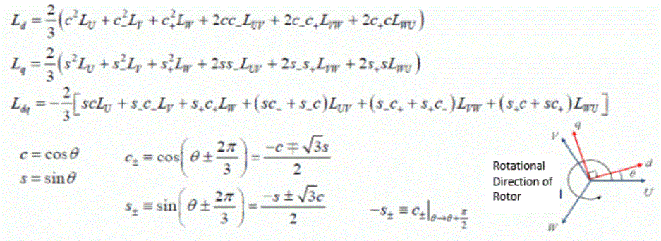
Calculates the Inductances Ld of the d-axis, Lq of the q-axis, and the mutual inductance Ldq and lqd of the dq-axis. -
Lu, Lv, and Lw
Calculates the 3-phase inductance matrix elements Lu, Lv, Lw, Luv, Lvw, and Lwu.
It is in the [Analysis Condition Setting] dialog box. See also [How to Set Analysis Condition].
|
Setting Item |
Notes |
|
Characteristics to Calculate |
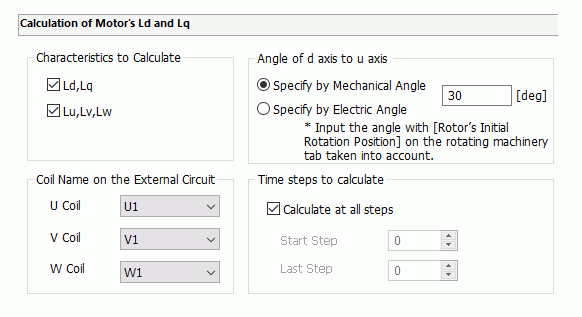
Ld and Lq Calculates the Inductances Ld of the d-axis, Lq of the q-axis, and the mutual inductance Ldq and lqd of the dq-axis. Calculation is executed with the specified timesteps.
Lu, Lv, and Lw Calculates the 3-phase inductance matrix elements Lu, Lv, Lw, Luv, Lvw, and Lwu. Calculation is executed with the specified timesteps. The Settings Required for Calculation
|
|
Coil Name on the External Circuit |
Specifies coil names of FEM components in the external circuit for U coil, V coil, and W coil of the 3-phase AC unit.
|
|
Angle of d-axis to u-axis |
Used for calculating Ld and Lq.
Sets the angle of d-axis to u-axis at the initial time. With reference to the u-axis, if the d-axis is advanced, set the positive value. If it is behind, set the negative value.
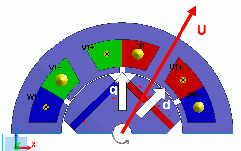
Definition of Each Axisd-axis: Center axis of permanent magnet (magnetic flux direction generated by magnetic pole) q-axis: Axis between permanent magnets (axis magnetically crossing the d axis at the right angle) u-axis: Magnetic flux direction generated by U-phase coil ExampleIn the diagram below, the mechanical angle of the d-axis to the u-axis is -15[deg].
|
|
Timesteps to calculate |
Sets the number of timesteps for various calculations. The more number of timesteps, the longer the calculation time.
|
Ld and Lq Equations