


|
Home / Technical Notes / Fluid Analysis/Fluid-Thermal Analysis / Boundary Condition of Fluid Analysis
Boundary Condition of Fluid Analysis
An idea of how to set the boundary conditions for the fluid analysis is explained.
For the details of the setup, please refer to [Fluid tab (Fluid-Thermal tab)].
1. Boundary Condition around the Fluid
The boundary condition around the fluid is either wall boundary condition or flow boundary condition.
These conditions are explained below.
How to treat the areas where the boundary condition is not set up are also explained.
1.1 Wall Boundary Condition
It is set to the face where inflow and outflow of fluid do not occur.
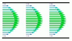
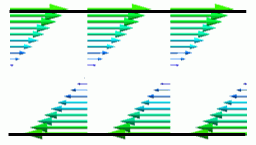
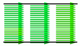
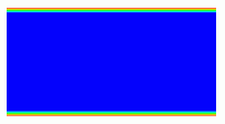
There are three conditions: Solid Wall [Static Wall], Solid Wall [Moving Wall], and Slip Wall.
The differences are described below.
|
|
Solid Wall [Static Wall] |
Solid Wall [Moving Wall] |
Slip Wall |
|
Flow Velocity on the Wall Face |
Sets to zero in every direction
|
Along the wall face: Set to specified value Sets to zero in the normal direction
|
Sets to zero only in the normal direction
|
|
Shear Stress on the Wall Face |
Occurs according to the flow velocity
|
Occurs according to the wall face speed and flow velocity |
Does not occur
|
|
Used as |
A boundary with solid. (automatically set for the boundary with a solid body), An outer boundary condition for an internal flow |
Surface of the moving object |
Virtual wall without inflow and outflow Symmetric boundary condition, Outer boundary condition for an external flow |

1.2 Flow Boundary Condition
It is set to the face where inflow and outflow of fluid occur.
There are inlet, outlet, and inlet/outlet.
The inlet is set to the face where the inflow is known to occur. The outlet is set to the face where the outflow is known to occur.
The inlet/outlet is set to the face if it is not known if the fluid flows in or out.
The flow boundary condition is classified as the forced boundary and the natural boundary. The forced boundary creates the inflow and outflow forcibly. The natural boundary is the boundary other than the forced boundary.
Boundary condition setting is explained in detail in [4. Combination of Boundary Conditions].
1.3 Automatic Boundary Condition Setting
If there is a face around the fluid, to which the wall boundary condition or the flow boundary condition is not set, the boundary condition is set automatically.
The boundary with a body having solid material specified
A solid wall is set automatically.
Other boundaries
The condition set in [Outer boundary condition] is applied.
The default outer boundary condition is determined automatically based on the setting of internal or external flow and the configuration of the model.
2. Basic Setting Steps
Normally, [1. 3 Automatic Boundary Condition Setting] above is utilized for setting as in the following steps.
Step 1. Select either internal flow or external flow in the analysis condition.
Generally, the following three are used for the surrounding boundary condition. (Refer to 3. Internal Flow and External Flow)
- Wall boundary condition [solid wall]
- Wall boundary condition [slip wall]
- Flow boundary condition [inlet/outlet: natural inflow/outflow]
If [Internal Flow] is selected, [Solid Wall] is applied automatically to the outer boundary.
If [External Flow] is selected, [Natural Inflow/Outflow] for Inlet/Outlet or [Slip Wall] is automatically applied to the outer boundary.
(The selection depends on inflow or outflow setting in Step 2. If the setting is [One-way Forced Convection], the outer boundary condition is set to [Slip Wall].)
Step 2. Select the faces for inflow and outflow, and set the flow boundary condition.
The inlet boundary condition and the outlet boundary condition must be set at least one each.
3. Internal Flow and External Flow
3.1 Boundary Condition Setting for the Internal Flow
The flow in the domain surrounded by the solid is called internal flow.
For example, the flow in a pipe or a casing is the internal flow.
Forced convection
To analyze the internal flow, a body for the flow path is created. The inlet boundary condition and the outlet boundary condition are set to the faces where the flow is coming in and going out respectively.
As the flow path body is surrounded by the solid, the solid wall is a proper outer boundary condition.
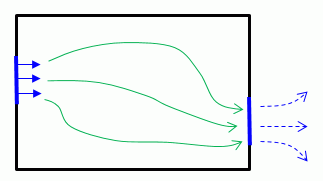
Blue lines: Flow boundary condition, Black lines: Solid wall boundary condition
Examples:
[Tutorial]
[Example 1: Laminar Flow between Parallel Plates]
[Example 2: Turbulent Flow between Parallel Plates]
Closed domain
The domain surrounded by the solid without inlet and outlet is the closed domain.
A fluid body is created for the analysis in the closed domain.
Solid wall is a proper outer boundary condition.
Enclosing the flow path with solid is also a good setting.
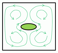
Black lines: Solid wall boundary condition
The flow in the closed domain will be treated differently depending on whether or not the buoyancy is taken into account.
If the buoyancy is taken into account
The natural convection will be calculated.
If the buoyancy is not taken into account
The internal flow will not be calculated. In the fluid-thermal analysis, only heat transfer in the fluid will be calculated.
If the closed domain is small and the effect of the natural convection is small, the calculation time can be reduced by setting the buoyancy not to be taken into account.
3.2 Boundary Condition Setting for the External Flow
The external flow is a flow around the solid.
A typical example is the flow around an airplane.
The boundary conditions are set differently for the one-way forced convection and the natural convection.
One-way Forced Convection
Surround the solid body with a box. Set the inlet boundary condition to the entire face where the flow comes in. The inlet type is forced inflow with velocity specified.
Set the outlet boundary condition to the entire face where the flow goes out. The outlet type is natural outflow.
The uniform flow flows in and out in the analysis domain. The appropriate outer boundary condition is the slip wall.
Select slip wall for the outer boundary condition and set the slip wall boundary condition.
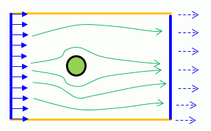
Blue lines: Flow boundary condition, Black lines: Solid wall, Orange lines: slip wall
Examples:
[Example 3: Flow around Cylinder]
[Example 1: Cooling of Plate by Forced Convection (Laminar Flow)] (Fluid-thermal analysis)
[Example 2: Cooling of Plate by Forced Convection (Turbulent Flow)] (Fluid-thermal analysis)
[Example 3: Cooling of IC by Forced Convection] (Fluid-thermal analysis)
Natural convection
Surround the solid body with a box.
Natural inflow/outflow is the appropriate outer boundary condition because the fluid flows freely in and out of all surrounding faces.
In the boundary condition type, select [Inlet/Outlet], then select Natural Inflow/Outflow.
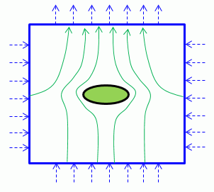
Blue lines: Flow boundary condition
Examples:
[Example 6: Cooling of IC by Natural Convection] (Fluid-thermal analysis)
[Example 8: Transient Analysis of Cooling of IC with Initial Values Obtained in the Steady-state Analysis] (Fluid-thermal analysis)
3.4 Inflow Turbulent Flow Rate for the Internal and External Flows
To perform the turbulent analysis, the turbulent flow energy K and the energy dissipation rate ε must be specified for the incoming fluid.
In the case of the internal flow, it is assumed that the incoming flow is relatively strong due to the turbulence which was developed through the flow path.
In the case of the external flow, it is assumed that the incoming flow is relatively weak because the velocity is uniform.
Femtet can specify the incoming turbulent flow rate by automatic calculation.
It judges if the flow is internal or external. For the internal flow, the strong turbulent flow is assigned. For the external flow, the weak turbulent flow is assigned.
For the details of the setup, please refer to [Fluid tab (Fluid-Thermal tab)].
4. Combination of Flow Boundary Conditions
To assign the flow to the model, the inlet and the outlet must always be set .
It is because the analysis is performed assuming that the fluid incompressible, and that the inflow rate and outflow rate are balanced.
If the inflow and outflow take place at more than two places, the inlet and the outlet must be set to at least one place each.
Also, for a stable calculation, it is necessary to set the boundary which gives the flow forcibly as the type of inlet and outlet such as forced inflow and forced outflow. At the same time, the natural boundary must always be set.
If the inflow and outflow take place at more than two places, the forced boundary and the natural boundary must be set to at least one place each.
In the analysis where the buoyancy is taken into account, however, analysis can be performed without the forced boundary because the flow is forcibly generated by the buoyancy.
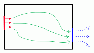
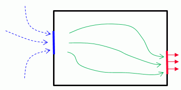
The recommended combinations are shown below.
|
Inlet Type |
Outlet Type |
Example |
|
Forced Inflow (Velocity Specified) |
Natural Outflow |
Red lines: Forced inflow, Blue lines: Natural outflow |
|
Forced Inflow (Specify flow rate) |
Natural Outflow |
|
|
Forced Inflow (Pressure Specified) |
Natural Outflow |
|
|
Forced Inflow (Fan) |
Natural Outflow |
|
|
Natural Inflow |
Forced Outflow (Velocity Specified) |
Blue lines: Natural inflow, Red lines: Forced outflow
|
|
Natural Inflow |
Forced Outflow (Specify flow rate)
|
|
|
Natural Inflow |
Forced Outflow (Pressure Specified) |
|
|
Natural Inflow |
Forced Outflow (Fan) |
Set [Inlet/Outlet] as a boundary condition to the face if it is not known whether the fluid is flowing in our out.
With this setting, if the fluid flows in, the same state as the natural inflow (boundary condition type: inlet, inlet type: natural inflow) is created, and if the fluid flows out, the same state as the natural outflow (boundary condition type: outlet, outlet type: natural outflow) is created.
This setting works in place of the natural inflow and the natural outflow.
5. Fan Boundary Condition
In the case of sending or extracting the wind by fan to or from the domain where the pressure loss is large, it takes the larger energy. The flow rate, therefore, is limited even if the fan rotates at the same rate.
The fan boundary condition takes this nature into account for analysis.
See [Example 4: Forced-outflow Fan] for more information.
5.1 P-Q Characteristics
P-Q characteristics is a parameter to represent the fan's characteristics.
The pressures difference and the volumetric flow rates before and after the fan are represented. Usually, the information is described in the product catalog of fan.
The differential pressure is at its maximum when the volumetric flow rate is zero. The differential pressure becomes smaller as the volumetric flow rate goes larger.
The pressure loss in the analysis domain becomes larger in proportion to the volumetric flow rate.
It crosses with the P-Q characteristics at the point called working point.
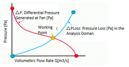
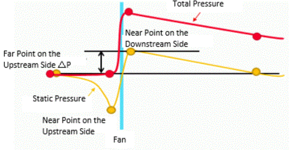
There are two methods to define the differential pressure. One is to measure the static pressures at the near points on the upstream and the downstream sides of the fan.
Another way is to measure the static pressures at the far points on the upstream and the downstream sides of the fan.
Femtet employs the latter method since it used generally.
The latter method means that the static pressure at the near point on the upstream side and the total pressure at the near point on the downstream side of the fan are measured.
5.2 Inflow Fan
The pressure rise is given to the environment according to the inflow rate.
Femtet calculates the environment pressure as 0[Pa]. It performs the calculation so that the static pressure and the flow rate on the boundary condition (near point on the downstream side) are as specified in the table.
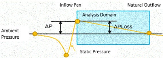
The analysis is executed with the volumetric flow rate where the pressure rise and the pressure loss in the analysis domain become almost equal.
To take into account the swirling flow in the downstream of the axial flow fan, specify the number of rotations and slip factor.
The flow velocity in tangential direction to the normal axis of the inflow is given by the following equation.

5.3 Outflow Fan
The pressure drop is given to the environment according to the outflow rate.
Femtet calculates the environment pressure as 0[Pa]. It performs the calculation so that the total pressure and the flow rate on the boundary condition (near point on the upstream) are as specified in the table.
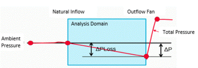
The analysis is performed with the volumetric flow rate at the working point where the pressure drop and the pressure loss in the analysis domain become almost equal.