


|
Home / Technical Notes / Fluid Analysis/Fluid-Thermal Analysis / Notes When Creating Layer Meshes
Notes for Creating Layer Meshes
Typically, layer meshes created properly improve convergence and accuracy for calculations in the fluid/fluid-thermal analysis. However, some layer meshes may degrade the convergence and accuracy.
The causes and methods to modify the model are explained herein.
1. Layer Blocking Point
In specific points, the layer meshes cannot be created.
The causes and methods to modify the model are explained herein.
1.1 Layer Blocking Point
In specific points, the layer meshes cannot be created.
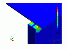
In the vicinity of the layer blocking point, meshes of poor quality may be created. These meshes can cause poor convergence.
Even though a warning about the layer blocking point is displayed, the calculations will be performed.
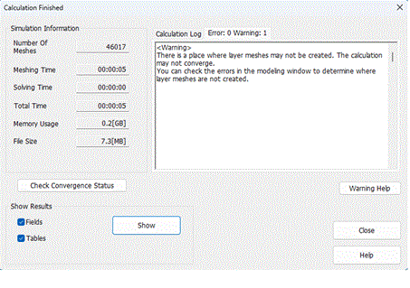
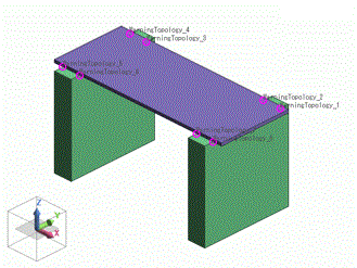
In the model window, you can check for layer blocking points.
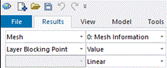
You can also check for layer blocking points by selecting mesh and layer blocking point on the result tab.
1.2 How to Modify the Model Where Layer Meshing Fails Locally
If layer meshes are not created locally, there may be two causes.
The cause is displayed in the output window.
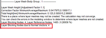
(1) Layer Blocking Point due to Normal Vectors
The cause is that the normal direction directed inward into a fluid is not uniquely determined at a specific point.
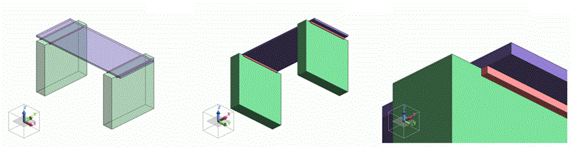
As an example, the calculation of the flow around a model where a plate is supported by two blocks is explained as follows.
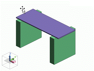
The portions at which the blocks contact the plate are the layer blocking points.
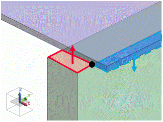
Among the normal vectors of the faces each including the layer blocking point, the normal vectors of the top face of the box (red line below) and the normal vectors of the bottom face of the plate (light-blue dotted line below) point in opposite directions.
Since the point has normal vectors in opposite directions, the normal direction directed inward into a fluid cannot be determined and then layer meshes cannot be created.
As one solution, you can add a body that is small enough not to affect the flow, at the contact points between the plate and the boxes.
Two examples are shown below.
Example 1: Add a box around the point
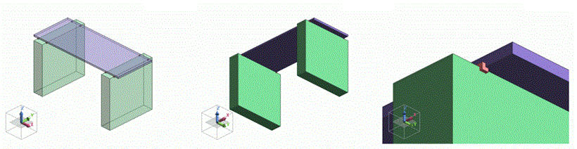
The points with upward and downward normal vectors are separated, so that opposite normal vectors are prevented from overlapping.
Example 2: Add a box so as to contact the point
The point with a downward normal vector is shifted, so that opposite normal vectors are prevented from overlapping.
Example 2's model is easier to modify than example 1's.
(2) Layer Blocking Point due to Layer Height Adjustment
If the layer height adjustment results in an extraordinarily low layer height, layer meshing will be blocked.
The warning is displayed.
An extraordinarily narrow gap is highly likely to cause layer blocking.
As one solution, check your model to modify it.
2. Specific Inflow/Outflow Faces
Types of faces for layer meshing and how to handle respective faces are explained.
In the vicinity of the specific inflow/outflow faces, meshes of poor quality may be created. These meshes may degrade the convergence and accuracy.
2.1 Face Type
To generate layer meshes, faces are categorized into three types below.
Type |
Required Condition |
How to Create |
|---|---|---|
|
Wall Face |
・Wall boundary on fluid surface |
Create layer meshes from the surface inward into the fluid. |
|
Inflow/Outflow Faces |
・Fluid boundary on fluid surface |
Do not create layer meshes |
|
Specific Inflow/Outflow Faces. |
・Fluid boundary on fluid surface |
Refine the surface by layer meshing. |
Examples of specific inflow/outflow faces are shown below.
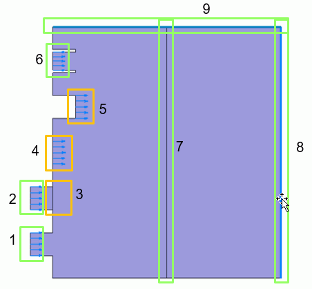
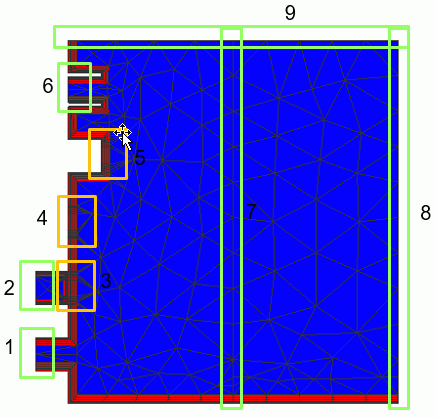
Number |
Type |
Required Condition |
|---|---|---|
|
1, 2, 6 |
Inflow/Outflow Faces |
・Fluid boundary on fluid surface (inflow boundary) ・Convex toward the fluid domain. |
|
3 |
Specific Inflow/Outflow Faces. |
・Fluid/fluid boundary ・Flat toward the fluid domain on the right |
|
4 |
Specific Inflow/Outflow Faces. |
・Fluid boundary on fluid surface ・Flat toward the fluid domain on the right |
|
5 |
Specific Inflow/Outflow Faces. |
・Fluid boundary on fluid surface ・Concave toward the fluid domain on the right |
|
7 |
Inflow/Outflow Faces |
・Fluid/fluid boundary ・Convex toward the fluid domain on the right and left |
|
8 |
Inflow/Outflow Faces |
・Fluid boundary on fluid surface (outflow boundary) ・Convex toward the fluid domain. |
|
9 |
Inflow/Outflow Faces |
・Wall boundary(slip wall) |
2.2 How to Modify Models with Specific Inflow/Outflow faces
In the vicinity of the specific inflow/outflow faces, meshes of poor quality may be created. These meshes may degrade the convergence and accuracy.
Examples of modifying the model are described below.
・If the fluid/fluid boundary is a flat shown as 3 in the diagram above.
Unite bodies to eliminate the fluid/fluid boundary. (Changed to a state shown as 1 in the diagram)
・If the fluid surface is a flat shown as 4 in the diagram above.
Extrude the inflow/outflow face outward from the fluid and set a boundary condition on the extruded face. (Changed to a state shown as 1 in the diagram)
・If the fluid surface is a concave shown as 5 in the diagram above.
Modify the concave into the shape seemingly given by folding back the concave (shown as 6 in the diagram above), and assign a boundary condition to the folded back surface.