


|
Home / Technical Notes / Electromagnetic analysis / Analysis Condition / Propagation mode transformation
Propagation Mode Transformation
This function is available for the 3D harmonic analysis of electromagnetic waves.
A model that has the multiple integral paths can be analyzed. The multiple propagation modes at the ports are obtained as a mode of a single port.
Also, the differential pair and ground can be set to the propagation mode when defining the integral paths.
This function is useful when analyzing a model in which, like the differential lines, the electrodes are close to each other at a port or the ground is electrically isolated.
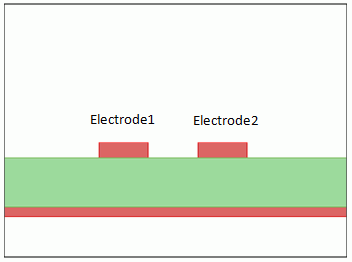
Fig.1 Differential Lines
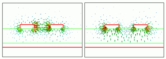
Fig.2 Differential Mode (left) and Common Mode (right) of the Differential Lines
Below is a typical problem if there is only one integral path.
By analyzing a model in Fig. 1, the differential and common modes are obtained as shown in Fig. 2.
Characteristic impedance (Zpv) of each mode is calculated with the voltage along the integral path.
The electric fields of the two modes are intensified at the different locations. This makes it difficult to accurately calculate the characteristic impedances of the two modes with one integral path.
It also means that calculation of S-parameters (mixed mode S-parameters) with two modes taken into account cannot be performed accurately.
To analyze the differential and common modes with only one integral path, you must create an analysis project for each integral path (propagation mode).
See the example below for the details.
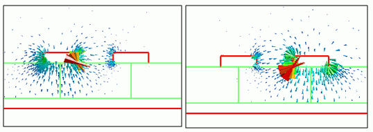
Fig.3 Modes Obtained by Propagation Mode Transformation
On the other hand, the propagation mode transformation allows multiple integral paths which are suitable for each mode.
It enables the accurate analysis for multiple propagation modes.
The solution obtained by this function is for the single port of each electrode.
If this function is applied to the model in Fig. 1, the obtained solution is for the single port which feeds each electrode as in Fig. 3.
In the left figure of Fig.3, the voltage is applied only on Electrode 1. In the right figure of Fig.3, on the other hand, the voltage is applied on Electrode 2.
To see how the electricity is supplied with each mode, go to Field Superposition Setting, and set either 1, -1, or 1, 1 for each mode.
There are two methods to convert the obtained S-parameters to mixed-mode S-parameters;
One is balance conversion of SYZ matrix, and the other is differential pair setting for the integral path.
See the following for reference.
- Example 19: Differential Lines with Connector for balance conversion of SYZ matrix.
- Example 23: Mixed-Mode S-Parameters Analysis of Differential Lines for differential pair setting.
This function also enables the setting of ground mode to each mode.
If the ground mode is given, the electrode is regarded as ground (electric wall). It can be treated as an electrically isolated ground electrode.
See below for reference.
When using this function, be aware of the following.
Note 1: Setting of ports
Set up the integral path and the reference impedance in the port setting dialog box.
The reference impedances of all ports must be the same.
Note 2: Setting of integral paths
The integral path must be set for each electrode. In the port setting dialog box, set the integral path corresponding to the mode (feeding mode for electrode) that is taken into account.
Each integral path can be distinguished by assigning name.
Note 3: Non-propagating mode
The error E3094 occurs if the non-propagating mode is selected during the adaptive meshing of the port.