


|
Home / Technical Notes / Electromagnetic analysis / Boundary Condition / Avoiding the Parallel Plate Mode
Avoiding the Parallel Plate Mode
How to avoid the parallel plate mode in the 3D electromagnetic harmonic analysis is described below.
When the ports are attached to strip lines or coplanar waveguides, the parallel plate mode might be obtained in the electromagnetic waves 3D harmonic analysis. This mode actually don't exist.
To avoid this problem, set "electric wall"on the edges of strip lines or coplanar waveguides as shown below.
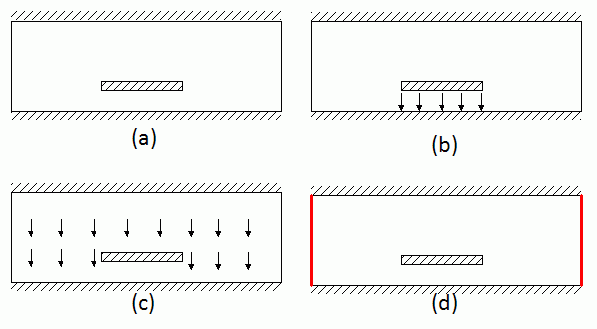
Figure 1 shows the strip line. The hatched area represents conductor or electric wall.
Sometimes, the parallel plate mode (Figure 1c) is obtained instead of the propagation mode (Figure 1b).
To fix the problem, connect the upper and the lower conductors with electric wall as in Figure 1d. In this figure, the red lines represent the "electric wall" boundary condition.
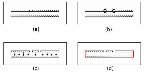
Figure 2 shows the coplanar line with ground. Again, the parallel plate mode (Figure 2c) may appear instead of the coplanar mode (Figure 2b).
To fix the problem, connect the upper and the lower conductors with electric wall as in Figure 2d.
 |
|
Figure 1 Strip line
|
 |
|
Figure 2 Coplanar line |