|
Home / Modeling / Drawing Process / Grids
Grids
Show Grids
On the [View] tab,

 switches on/off the grids.
Set up Grids
On the [View] tab,
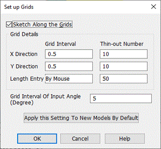
select [Set up Grids]  . The dialog for the grid setup will show up.
|
Items |
Notes |
|
|
Sketch along the grids |
Enables the sketching along the grids. |
|
|
Grid details |
X direction Y direction |
Sets the grids along the coordinate axes. The directions are based on the current drawing plane. Example: If the current drawing plane is the YZ plane, the X/Y directions for grids are the Y/Z directions of the YZ plane.
|
|
Length direction |
Sets the grids for the length such as radius and height. |
|
|
Grid interval Thin-out number |
Sets the grid interval of each direction by the real number. Thin outs the grids for display by entering an integer. If n is entered, every n-th grid will be displayed. |
|
|
Grid interval of input angle (degree) |
Specifies the angle interval of Rotate/Revolve. For example, if 5 is entered, the angle for Rotate/Revolve can be entered with 5[deg] interval. |
|
|
Apply this setting to new models by default |
Applies the current settings to a newly created model by default. |
|
Examples
|
|
The model is created on the YZ plane.
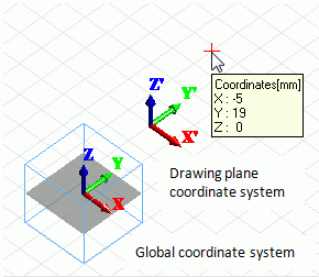
The grids are displayed on the drawing plane. The axes indicated there are those of the drawing plane.
|
|
|
The left figure shows the grid thin-out for display.
The grid display interval is "Grid interval" multiplied by "Thin-out number".
The setting for the figure is as follows.
* X direction: Grid interval, 0.5 x Thin-out number, 5 = 2.5
* Y direction: Grid interval, 0.5 x Thin-out number, 10 = 5.0 |
|
|
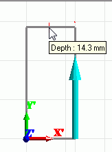
The left figure is an example of "Length entry by mouse".
The length could be width, depth, or height. The height is entered by mouse in this example.
The point at the tip of the arrow indicates the height.
The grid display interval is "Grid interval" multiplied by "Thin-out number". |