General
Home / Examples / Coupled Analysis / Fluid-Thermal Analysis [Bernoulli/Watt] / Example 14: Cooling by Fan
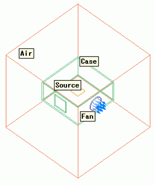
A heat source is placed inside the case. A fan on the case cools the heat source.
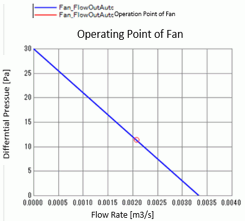
The fan pressure and the flow rate are determined according to the pressure loss. The operating point of the fan can be output as well.
The monitoring values are used for convergence judgment.
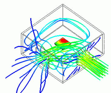
The temperature distribution and the heat flux vectors are solved.
The results can be viewed by the simultaneous display of temperature contours and streamlines.
Unless specified in the list below, the default conditions will be applied.
Results will vary depending on Femtet version and the PC environment.
Item |
Settings |
Analysis Space |
3D |
Model Unit |
m |
Item |
Setting |
Solver |
Fluid Analysis [Bernoulli] Thermal Analysis [Watt] |
Analysis Type |
Fluid Analysis: Steady-state Analysis Thermal Analysis: Steady-state Analysis |
Detailed Setting |
Convergence Judgment by Monitoring Value Enable |
Tab |
Monitoring Quantity |
Settings |
Monitoring |
Temperature |
Monitoring Domain: Select [Body Attribute] Then click [Add]. |
Volumetric Flow Rate |
Monitoring Domain: Select [Body Attribute] |
The heat dissipation of the heat source inside the case is calculated.
A fan and a vent are set on the case.
Body Number/Type |
Body Attribute Name |
Material Name |
3/Solid |
Source |
Si |
5/Solid |
Case |
001_Al * |
6/Solid |
Fan |
000_Air * |
7/Solid |
Air |
000_Air * |
* Available from the material DB
Body Attribute Name |
Tab |
Setting |
|||||||||
Fan |
Fluid |
Inflow and Outflow Faces are set to the both sides of the circular model.
Fluid Body Type: Specify flow Inlet/Outlet Type: Fan P-Q Characteristics
|
Boundary Condition Name/Topology |
Tab |
Boundary Condition Type |
Setting |
Outer Boundary Condition |
Fluid-Thermal |
Inlet/Outlet |
Natural Inflow/Outflow Inflow Temperature: Use ambient temperature (25 [deg]) |
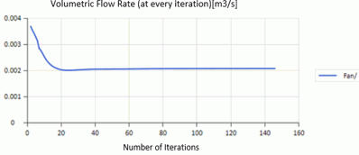
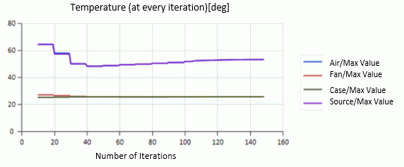
The calculation was terminated by the monitoring values for convergence judgment before the residual converges.
Below are the transitions of the volumetric flow rate of the fan and the maximum temperatures of each body attribute that are predetermined as monitoring values.
(Displayable by clicking Check Convergence Status button in the dialog box after the analysis finishes)
Since the results are almost constant, it can be interpreted to be acceptable to terminate the calculation before the residual fully converges.
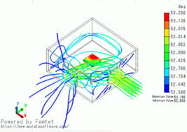
The figure below shows the streamlines and the contours of temperature distribution of the heat source at the same time. The contour field of the case is hidden.
The air flows into the case from the vent and flows out through the fan.
The operating point of the fan can be viewed in the result table.
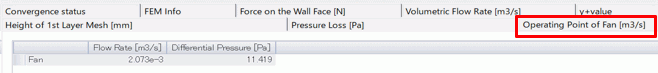
By displaying on the graph, the operating point can be located on the P-Q characteristic.