General
Home / Examples / Stress Analysis [Galileo] / Example 6: Deformation of Spring Plate
The deformation of a spring plate under forced displacement is analyzed.
If an object is deformed beyond the limit of its elasticity, the large deformation occurs. It is treated as a nonlinear problem.
See Technical Note Analysis of Large Deformation (Geometric Nonlinearity).
The distributions of displacement and stress are solved.
Unless specified in the list below, the default conditions will be applied.
Results will vary depending on Femtet version and the PC environment.
Item |
Settings |
Analysis Space |
3D |
Model Unit |
m |
To solve the deformation caused by static load, the static analysis is selected.
As the element has rotation and large strain involved, [Large Displacement] option needs to be selected as well.
This will activate Galileo's nonlinear solver.
Item |
Settings |
Solver |
Stress Analysis [Galileo] |
Analysis Type |
Static Analysis |
Large Deformation |
Select [Large Displacement]. |
The spring plate is a rectangular solid body. The material is polycarbonate.
The plate is mechanically fixed at one end.
The forced displacement is applied on the other end.
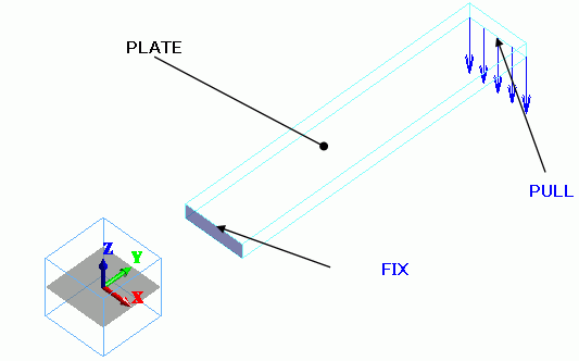
Body Number/Type |
Body Attribute Name |
Material Name |
0/Solid |
PLATE |
000_Polyethylene(PE) * |
* Available from the material DB
Boundary Condition Name/Topology |
Tab |
Boundary Condition Type |
Settings |
FIX/Face |
Mechanical |
Displacement |
Select all X/Y/Z components. UX=0, UY=0, UZ=0 |
PULL/Edge |
Mechanical |
Displacement |
Select the Z component. Z = -15 [m] |
The simulation is divided in 20 substeps. Calculate each step with a gradually larger displacement.
20 results are output for the steps between 0.05 [Step] and 1 [Step].
The number of substeps is 20 by default. It can be adjusted on the Step/Thermal Load tab.
All the results of substeps are output by default. Only the final result of 1 [Step] can be output.
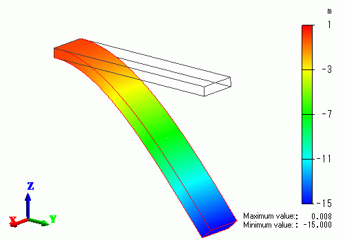
The contour diagram shows the Z displacement at 1 [Step].
The scale adjustment ratio on the Displacement tab of the Graphics Setup is set to 1.
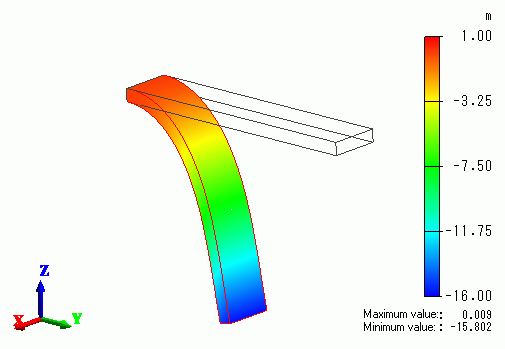
The tip of the plate is curling towards -Y direction.
If [Show all results summary] is selected, the external force and reactive force are listed in the table below.
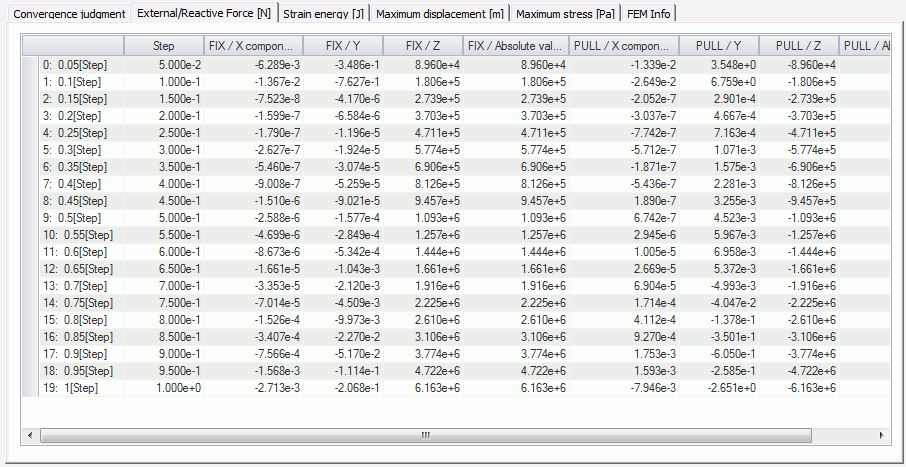
The reactive force at the boundary condition FIX is a total of 6.163e+6 [N] in + Z direction at 1 [Step].
The external force at PULL is a total of 6.163e+6 [N] in -Z direction at 1 [Step].
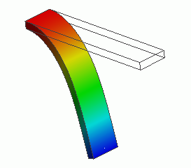
For comparison, the displacement without Large Displacement is calculated and the result is shown below.
The tip is not curving back downward towards the root. That is unnatural.