Home / Examples / Stress Analysis [Galileo] / Example 42: Stress of Rod Inserted into Ring
A shaft is inserted into a ring. The outer diameter of the shaft is slightly larger than the inner diameter of the ring.
Ring's outer diameter, d2 = 50mm, Ring's inner diameter (Shaft’s outer diameter ) after insertion, d1 = 40mm
The difference, tightening allowance, between the shaft’s outer diameter and the ring’s inner diameter, 2*δ, is 0.2 mm.
The distributions of displacement and stress are solved.
Unless specified in the list below, the default conditions will be applied.
The analysis can be performed using overlapping meshes instead of initial strain as in Example 68.
Results will vary depending on Femtet version and the PC environment.
Item |
Settings |
Analysis Space |
3D |
Model Unit |
mm |
Item |
Settings |
Solver |
Stress Analysis [Galileo] |
Analysis Type |
Static Analysis |
Options |
N/A |
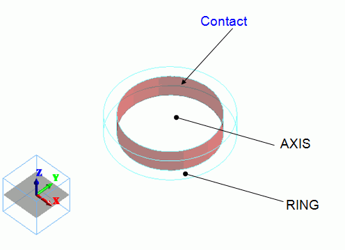
By creating two cylindrical solid bodies with different diameters and subtracting the smaller cylinder from the larger one using boolean operations,
models of a shaft and a ring are created.
The inner face of the ring is set with the simple contact boundary condition.
Body Number/Type |
Body Attribute Name |
Material Name |
0/Solid |
AXIS |
001_Al * |
0/Solid |
RING |
001_Al * |
* Available from the material DB
Taking into account the tightening allowance, the initial strain of 0.005, which comes from 0.2 [mm] / 40 [mm], is set to AXIS.
Body Attribute Name |
Initial Strain |
AXIS |
Axial strain/Isotropic/0.005 |
RING and AXIS are not adhered. They are in simple contact.
Boundary Condition Name/Topology |
Tab |
Boundary Condition Type |
Settings |
CONTACT/Face |
Mechanical |
Simple Contact |
Automatic Judgment |
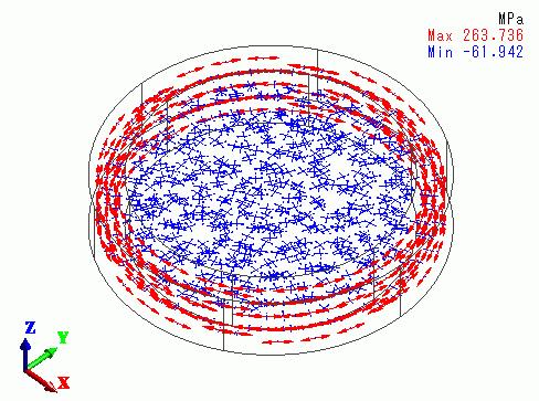
The vectors of the stress are shown below.
The ring gets tensile stress circumferentially, while the shaft gets compressive stress radially.
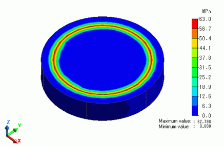
Theoretically, the pressure at the contact face, P, is given by the following.
P = Eδ(d2^2 – d1^2 ) / (d1 * d2^2)
E is Young's modulus [Pa], δ is the fitting differential [m], d2 is Ring's outer diameter [m], and d1 is Ring's inner diameter [m].
For this particular model,
P = 6.85 x 10^10 * 0.1 * ( 50^2 - 40^2 ) / ( 40 * 50^2)
= 6.165 x 10^7
The contour below shows the magnitude of pressure at the contact face.
This is close to the theoretical value, 6.165 x 10^7 [Pa].