


|
Home / Analysis Flow / Analysis with Meshes in Nastran Format
Analysis with Meshes in Nastran Format
Femtet can open a Nastran-format mesh file, generate the meshes,
and additionally set the analysis condition and boundary condition to perform analysis.
Available Analysis Types for Nastran Format
The analyses listed below can handle Nastran-format file with some exceptions.
Electric Analysis
Plating analysis is not supported.
Magnetic Transient Analysis [Luvens]
Rotating machinery is not supported.
Stress analysis
Boundary conditions of distributed edge load, simple contact, and contacting faces are not supported.
Piezoelectric Analysis
Boundary conditions of distributed edge load and open boundary are not supported.
Acoustic Analysis
All analysis conditions, except for the common limiting items, are supported.
Common Limiting Items
- Coupled analysis is not supported.
- Outer boundary condition setting other than by default is not supported.
- Discontinuous boundary is not supported.
- Periodic boundary is not supported.
- Symmetric boundary is not supported.
Preparation
Please prepare Nastran-format mesh file.
The file extensions are .bdf, .nas, and .dat.
BULK DATA entries
Femtet uses BulkData section only.
All the other sections will be ignored.
Items which can be used in Femtet are as follows.
- GRID (Nodes)
- TEMP (Boundary condition) *Equivalent item to node temperature which is set in Nastran.
- SPC (Boundary condition) *Equivalent item to node constraint which is set in Nastran.
**Used only in 3D**
- CTETRA (Tetrahedron 4-node or 10-node elements)
- CPYRAM (5- or 13-node square pyramid elements)
- CPENTA (Triangular prism 6-node or 15-node elements)
- CHEXA (Hexahedron 8-node or 20-node elements)
- PSOLID (Shaping properties of solid elements)
**Used only in 2D**
- CTRIA3 (3-node triangular elements)
- CTRIA6 (6-node triangular elements)
- CQUAD4 (4-node rectangular elements)
- CQUAD8 (8-node rectangular elements)
- PSHELL (Shaping properties of shell elements)
 Any other entries are not recognized by Femtet.
The physical data of TEMP and SPC are ignored.
Boundary condition settings
Femtet reads only node information from the boundary condition data in the Nastran-format mesh file.
The physical data will be ignored.
Set the dummy boundary condition of SPC(Node restraint condition) or TEMP(Node temperature) to the node.
Assign different ID numbers to the nodes which have different types of boundary conditions.
The type of boundary condition and numeric data must be specified later on in Femtet.
SPC and TEMP can be used at the same time but the different ID numbers must be given.
Procedure to Read File
1. Read file
Go to the [Tool] tab.
 and
and
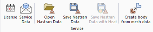
Click [Open Nastran Data]  .
.
Select a Nastran-format file in the dialog box.
Also specify the following.
|
Item |
Notes |
|
Analysis Space |
Select either 2D or 3D. (Default setting is 3D) |
|
Unit |
Select either m or mm. (Default setting is m) |
|
After Opening File |
- Show meshes - Standby Select one of the above. (Default setting is "Show meshes") |
A project file, which has the same project name as the original Nastran file, is opened and created.
If [Show meshes] is selected after opening the file, the mesh diagram will be displayed automatically.
2. Settings of analysis condition, body attribute, material property and boundary condition
2.1 Analysis Condition Settings
Set the analysis conditions.
On the [Result] tab  , click [Analysis Condition]
  .
.
If [Standby] is selected after opening the file,
click [Model] tab 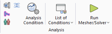 > [Analysis Condition]
  .
.
The [Analysis Condition Setting] dialog box will appear.
See [Analysis Condition Setting] for details.
 [Create air domain automatically] must be OFF in the mesh setting.
(No action is required unless the options for [Create air domain automatically] appear.)
The settings other than [Create air domain automatically] are not allowed to be changed.
2.2 Body Attribute Settings
The body attribute is given a name of [Vol_number].
The number is an ID number defined in the Nastran-format mesh file.
If the function to read the Nastran-format mesh file is used, the the body attribute can
be set up on the project tree only.
To change values, double-click the data on the tree or press <Enter> key.
The dialog box will appear for the setup.
If the values are not changed, the default values specific to the analysis solver will be applied.
See [Trees] for more information.
2.3 Material Settings
The material is given a name of [Mat_number].
The number is an ID number defined in the Nastran-format mesh file.
The setting procedure is same as the body attribute settings.
Please be sure the settings are done. Otherwise, the calculation may not be done normally.
2.4 Boundary Condition Settings
The boundary condition is given a name of [Bnd_number].
The number is an ID number defined in the Nastran-format mesh file.
The setting procedure is same as the material settings.
Since the form-factor model does not exist, it is not allowed to change the following
which will require mesh regeneration.
- Form factor
- Add or delete boundary conditions
- Mesh size
3. Execute Analysis
Execute analysis once the settings of analysis condition, body attribute, material, and boundary condition are completed.
On the [Result] tab , click [Run Mesher/Solver]  .
.
If [Result] tab is not displayed,
go to [model] tab and click [Run Mesher/Solver]  .
.