


|
Home / How to Set Body Attribute, Material Property and Boundary Condition / Body Attribute Tabs / Direction Tab
Direction Tab
The direction of the body is set on this tab.
It is shown in the [Edit Body Attribute] dialog box. See [How to Set Body Attribute/Material Property].
The detail is explained below.
-
The relationship of the coordinates of the anisotropic material (x, y, z) and the coordinates of the analysis space (X, Y, Z) is set
by vector or Euler angle. -
The magnetization direction of magnets
|
Setting Items |
Notes |
|
Direction Type |
Selects a specifying method from Vector, Euler Angle, Centripetal, Rotational, and Polar Anisotropic.
Centripetal is selectable only in the magnetostatic analysis and the magnetic-transient analysis. Rotational and Polar Anisotropic are selectable only in the magnetostatic analysis. (The magnetization direction of magnet specified) |
|
Vector (Parallel) |
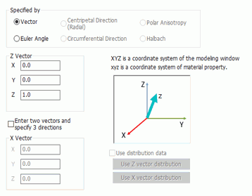
Sets a Z direction of the material if the anisotropic material has only one direction. For other cases, Z and X vectors are set.
Z Vector Specifies the Z direction of the material by vector. For example, in the case of the piezoelectric ceramics polarized in the Y direction, the vector is (0.0, 1.0, 0.0). The vector's magnitude is irrelevant, and (0.0, 5.0, 0.0) is acceptable as well. The magnetization direction of magnets can be also specified by vector.
X Vector [Enter two vectors and specify 3 directions] allows the entry of X direction. [Use distribution data] must be deselected in this case. If the entered X is not crossing with the Z direction at the right angle, the X direction of the analysis material does not match with the entered X vector. The material's direction for the analysis is determined as follow. The unit vectors of the entered z and x are Ez and Ex respectively. The z direction of the material always matches with the entered z vector. The material's Y direction is determined by (Ez x Ez), and X direction is given by ((Ez x Ex) x Ez).
Use Distribution Data Available for the piezoelectric analysis only.
Use Z vector distribution Available only in the piezoelectric analysis. By selecting [Use distribution data], the button becomes active. Click the button to open the dialog box.
Use X vector distribution Available only in the piezoelectric analysis. [Enter two vectors and specify 3 directions] allows the button become active. [Use distribution data] must be selected in this case. Click the button to open the dialog box.
|
|
Euler Angle |
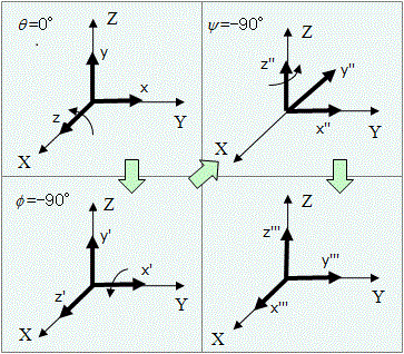
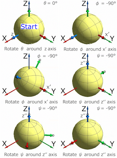
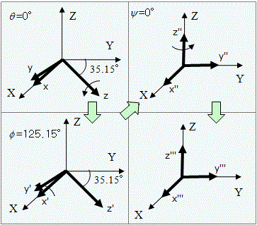
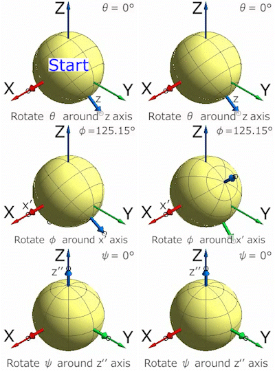
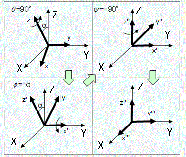
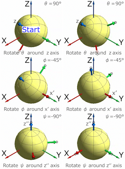
Converts the coordinates (x, y, z) of the material to the desired coordinates (X, Y, Z). It is required to rotate 3 times for the conversion.
(θ,φ,ψ) is Euler angle. Some examples are listed below.
The piezoelectric ceramics polarized in x axis (0, -90, -90) Note: It is recommended to use a vector more than Euler angle for specifying direction of a one-directional anisotropic material, such as piezoelectric ceramics, because of the easy usage.
AT-cut quartz (0, 125.15, 0)
Rotate by α around y axis
Default Setting: The coordinates for the material and the analysis space are identical.
|
|
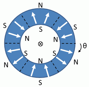
Centripetal Direction (Radial) |
Used to define the magnetization direction of magnets towards the center of the circle or cylinder. (Radially Anisotropic)
In this example, the number of poles is 6. Theta: Angle by Start Direction and Reference Axis.
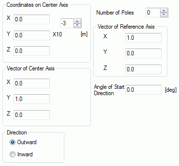
Coordinates on Center Axis: Specifies the coordinates of any point on the center axis of the circle. Y coordinate is not required for the 2D space.
Vectors of Center Axis: Sets the direction of the center axis of the circle. Y direction is fixed in the 2D space.
Direction: Sets either Outward or Inward.
Number of Poles: Selectable only in the magnetostatic analysis and the magnetic-harmonic analysis. Enter the number of poles around the circle. It counts clockwise from the vector of the center axis.
Vectors of Reference Axis Sets the start direction of the poles. Effective for 2 or more poles.
Start Direction and Angle of Reference Axis Sets the angle of the start direction measured from the reference axis. Effective for 2 or more poles.
|
|
Circumferential Direction |
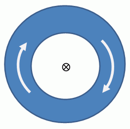
Defines the magnetization direction of magnets. Sets the direction towards the circumferential direction (or rotational direction) of the circle (or cylinder).
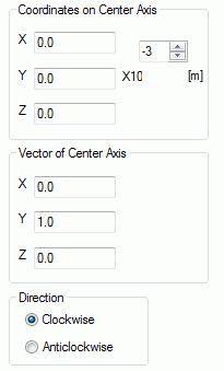
Coordinates on Center Axis: Specifies the coordinates of any point on the center axis. Y coordinate is not required for the 2D space.
Vectors of Center Axis: Sets the direction of the center axis of the circle. Y direction is fixed in the 2D space.
Direction: Sets either Clockwise or Anticlockwise looking in the direction of the vector on the center axis.
|
|
Polar Anisotropic |
Defines the magnetization direction of magnets around the circumference in polar anisotropy. Selectable only in the magnetostatic analysis and the magnetic-harmonic analysis.
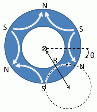
In this example, the number of poles is 6. R: Radius Theta: Angle by Start Direction and Reference Axis.
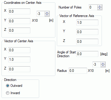
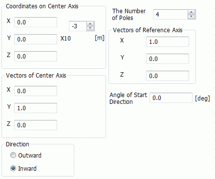
Coordinates on Center Axis: Specifies the coordinates of any point on the center axis. Y coordinate is not required for the 2D space.
Vectors of Center Axis: Sets the direction of the center axis of the circle. Y direction is fixed in the 2D space.
Direction: Sets either Outward or Inward.
Number of Poles: Sets the number of poles around the circle. It counts clockwise from the vector of the center axis.
Vectors of Reference Axis Sets the start direction of the poles.
Angle of Start Direction Sets the angle of the start direction measured from the reference axis.
Radius: Sets the distance from the center axis to each pole's center axis.
|
|
Halbach |
Specifies the magnetization direction of magnets. Sets the magnets in the Halbach array.
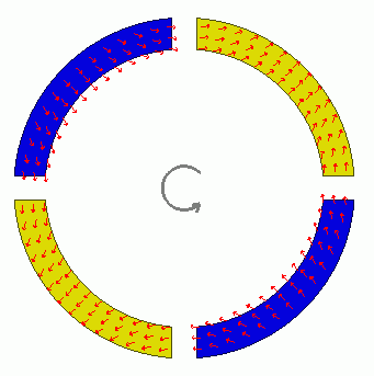
Example of outward direction with four poles
Coordinates on Center Axis: Specifies the coordinates of any point on the center axis. Y coordinate is not required for the 2D space.
Vectors of Center Axis: Sets the direction of the center axis of the circle. Y direction is fixed in the 2D space.
Concentration Direction of Magnetic Flux: Specifies the direction of a Halbach array. [Inward] is for the inward concentration of the magnetic field. [Outward] is for the outward concentration. In the case of motor, the direction is outward if the magnets are in the inner rotor, and it is inward if the magnets are in the outer rotor.
Number of Poles: Sets the number of poles around the circle. It counts clockwise from the vector of the center axis.
Vectors of Reference Axis Sets the start direction of poles.
Angle of Start Direction Sets the angle of the start direction measured from the reference axis.
|
|
Use Distribution Data |
Selectable if the direction type is vector in the piezoelectric analysis and the thermal analysis.
If Use distribution data is selected, Click the Distribution Data button to open the dialog box. |
-
Refer to Example. 3 Horseshoe Magnet for the settings on the direction tab.