


|
Home / How to Set Body Attribute, Material Property and Boundary Condition / Electromagnetic Analysis [Hertz] / Boundary Condition / Lumped constant
Lumped-Constant Boundary Condition
Lumped-constant boundary condition is set.
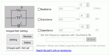
select Lumped Constant at the Boundary Condition Type on the Electric Tab of the Edit Boundary Condition dialog box. The lumped-constant boundary can be set to the sheet body only.
|
Setting Item |
Notes |
|
Resistance, Inductance, Capacitance |
The values of the lumped elements are set.
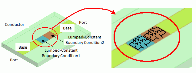
Set the lumped-constant boundary condition on the face between two conductors. Two lumped-constant boundary conditions can be set in a raw as in the figure below.
As shown below, the lumped elements (resistors, inductors, capacitors) are considered to be connected in parallel in each boundary.
|
|
Set the frequency response with Touchstone file |
The circuit information of the lumped-constant boundary is set by the Touchstone file. The supported file types are s1p, z1p, y1p, s2p, and y2p.
Please be aware of the following points.
Caution 1) The setting is only for the lumped-constant boundary, not for the complicated circuit like distributed circuit. (See the details)
Caution 2) In this setting, the fast sweep is not allowed.
Caution 3) The transient analysis is not supported.
Caution 4)
|
|
Integral Path Setting |
The integral path is for calculating the voltage and the current of the lumped-constant boundary. It is available for the transient analysis only.
The lumped-constant boundary is set to connect two conductors. Set the integral path so as to connect the two conductors on the lumped-constant boundary. In the transient analysis, the voltage between the conductors at each time and the current between the conductors are calculated.
If the integral path is not set, the voltage and the current of the lumped-constant boundary are not obtained.
|
 If the file is selected from this button, it will be registered in the absolute path.