|
Home / How to Set Body Attribute, Material Property and Boundary Condition / Boundary Condition Tabs / Electric Tab
Electric Tab
Boundary conditions relating to electricity are set on this tab.
It is in the [Edit Boundary Condition] dialog box. See [How to Set Boundary Condition].
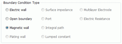
The link below explains the detail of each setting.
|
Boundary Condition Type |
Notes |
|||||||||||||||||||||||||
|
Electric Wall |
Specifies the boundary where the electric field lines are normal to the electric wall.
Detailed setting depends on the solver type. Magnetic solver [Gauss] requires no detailed setting. Electromagnetic solver [Hertz] requires no detailed setting.
|
|||||||||||||||||||||||||
|
Open boundary |
Specifies the open boundary. The detail is explained at Open Boundary Tab of the analysis condition.
|
|||||||||||||||||||||||||
|
Magnetic wall |
Specifies the boundary where the magnetic field lines are normal to the magnetic wall. |
|||||||||||||||||||||||||
|
Specifies the plating boundary. Specifies the plating boundary. It is selectable if "Perform the plating analysis" is selected in the analysis condition setting of the electric solver [Coulomb].
|
||||||||||||||||||||||||||
|
Specifies the conductor boundary with the finite conductivity. Sets the conductivity, the relative permeability, and the surface roughness (RMS). Selectable only for the electromagnetic analysis [Hertz].
|
||||||||||||||||||||||||||
|
|
Selectable for 3D electromagnetic-harmonic and electromagnetic-transient analyses, 3D magnetic analysis, and electric analysis.
■ Magnetic solver: For static analysis, the ports can be set inside the analysis space, For harmonic analysis, set the ports on the surface of the analysis space as they cannot be set inside the analysis space. for the harmonic analysis. ■ Electromagnetic solver: Further setting is required. |
|||||||||||||||||||||||||
|
Integral path |
Integral path is required to calculate the characteristic impedance in electromagnetic analysis (the waveguide analysis and the 3D harmonic analysis) and the induced electromotive force in magnetic analysis.
■ 3D harmonic and transient analyses: The integral paths with directions can be set in the Port Setup dialog box. That dialog box is more convenient than this tab, as the direction can be set there.
|
|||||||||||||||||||||||||
|
Specifies the lumped constants of LCR (inductors, capacitors, and resistors). Also possible to specify by Touchstone file. |
||||||||||||||||||||||||||
| Multilayer Electrode |
Specifies the electrode with multilayer structure.
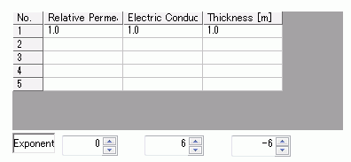
Two layers are defined in the table above and analysis is executed as follows. In the table, the first row is Layer No. 1 and the second row is Layer No. 2. Keep this layer order in mind.
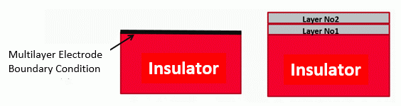
■ Electrode on the Edge of Analysis Domain Fig 1. Multilayer electrode boundary condition is set to the edge of the analysis domain as in the analysis model below. Layer No. 1 is set to the body. On top of it, Layer No. 2 is set. The thickness of Layer No. 2 specified in the table is not used in the analysis assuming that it is thick enough.
Fig 1. Analysis Model Fig 2. Analysis
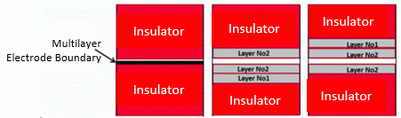
■ Electrode inside the Analysis Domain Fig. 3. Multilayer electrode boundary condition is set to the bottom side of the analysis domain.. Configuration of the multilayer electrodes is determined at Electromagnetic analysis options > "Multilayer Electrode Boundary Condition Setting" "Multilayer Electrode Boundary Condition Setting" by default is as in the Fig 4. The boundary condition is set to the lower body making it a multilayer structure. Only Layer No.2 is set on the upper and lower bodies. The structure of Fig 5 is another choice. In either case, the thickness is not taken into account for Layer No.2 The face which is set with boundary condition and its opposite face are treated differently.
Fig 3. Analysis Model Fig 4. Calculation Model: The body with multilayer electrode boundary condition is calculated as multilayer Fig 5. Calculation Model: The body with multilayer electrode boundary condition is calculated as single layer
Note 1: When setting boundary condition between bodies, boundary condition can be set by imprinting function. But this method cannot control which body is imprinted. The order of layers, therefore, cannot be controlled. The imprinting function is not suitable for setting the multilayer boundary condition. See How to Set Body Attribute Partially for reference. Note 2: Multilayer electrode boundary condition must be set to the insulator (material and conductivity tab). |
|||||||||||||||||||||||||
|
Electric Resistance |
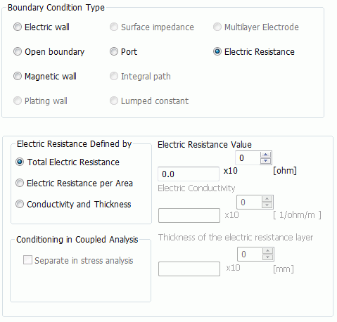
Sets the resistance on the contacting faces (or edges in 2D) of the two bodies.
The electric resistance is distributed evenly on all the specified faces. There are three input types available.
Total electric resistance: R [ohm] Electric resistance per area: Rs[m2 ohm] Conductivity and thickness: σ[1/ohm/m], d[mm]
The relationship of these types are expressed as follows where S[m2] is the area of boundary condition face.
R [ohm] = Rs / S = d / (σS)
|