


|
Home / How to Set Body Attribute, Material Property and Boundary Condition / Electric-Thermal Analysis [Coulomb/Watt] / Boundary Condition / Electric Wall in the Electric/Thermal Analysis
Electric Wall (Electric-Thermal Coupled Analysis)
Electric wall in the electric field - thermal coupled analysis can be set as follows.
Select Electric wall on Electric tab in the [Edit Boundary Condition] dialog box.
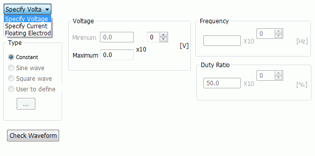
The electric field is set to be normal to the boundary. The type of electric wall can be selected in the combo box.
|
Setting Item |
Notes |
|
Electric Potential Specified |
Specifies the electric potential on the face of electric wall. |
|
Current Specified |
Inflow Face Specified current flows into the analysis domain from the face of electric wall.
Outflow Face Used for the current which is flowing out of the analysis domain. The electric potential on the face of electric wall is treated as 0V.
|
|
Floating Electrode |
Used to define the electrode whose electric potential is unknown.
In other words, the floating electrode is the unknown equipotential boundary. |
The voltage to apply or the current type can also be selected.
|
Setting Items |
Notes |
||||||||
|
Type |
Specifies the type of electric potential or current. Only Constant is selectable in the static analysis.
Press the Check Waveform button to see the frequency, the duty cycle, the electric potential, and the current.
|
||||||||
|
Frequency |
Specifies the frequency for the sine or square wave. |
||||||||
|
Electric Potential |
Specifies the maximum and the minimum value of the electric potential or current. When Constant is selected, enter the maximum electric potential only. |
||||||||
|
Duty Cycle |
The duty cycle [%] is specified as below for the square wave.
Duty cycle = Non-zero period/1 period
It should be be more than 0 and less than 100. |
||||||||
|
Check Waveform |
The voltage or the current waveform is displayed. You can verify the entered data visually. See [Waveform] for the details of waveform parameter definition. |
 to be clicked to open the