


|
Electric Wall (Piezoelectric and Electric Analyses)
Electric wall is set as follows.
Select Electric wall on Electric tab in the [Edit Boundary Condition] dialog box.
The electric field lines are normal to the electric wall.
|
Setting Items |
Notes |
|
|
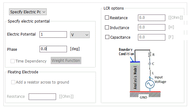
Electric Potential Specified |
Electric potential and phase |
Specifies the electric potential.
The phase can also be specified in piezoelectric harmonics analysis. The electric potential and the phase are based on the following formula:
Where the electric potential is V0 and the phase is θ,
V(t) = Re[V0 * exp[ j (ωt+θ )]] ω: Angular frequency t: Time Re: Real part j: Imaginary unit
|
|
Time dependency |
By selecting Time dependency and pressing the Weight Function button, the weight function table is activated to set the electric potential change over time. Selectable for the transient analysis of the piezoelectric solver. If deselected, the voltage will be constant over the analysis time.
|
|
|
Floating Electrode |
Used to define the electrode whose electric potential is unknown.
In other words, the floating electrode is the unknown equipotential boundary. The node on this boundary is given the same unknown number and treated as the equipotential.
When the calculation is completed, the electric potential of the floating electrode will be acquired.
"Add a resistor across to ground" is available in harmonic piezoelectric analysis. If this is selected and the resistor value is entered, the situation where a resistor is inserted between the floating electrode and the ground can be analyzed. |
|
|
LCR options |
Applicable only in the piezoelectric and harmonic analyses. If [Specify electric potential] is selected. L, C, and R can be added. Select the desired elements and enter their values.
L, C, and R are placed between the terminal of the input voltage and a boundary as illustrated in the dialog box. When any of L, C, and R are placed, the electric potential at the boundary will be different from the specified value.
|
|