|
Home / How to Set Body Attribute, Material Property and Boundary Condition / Joint Load Boundary
Joint Load Boundary
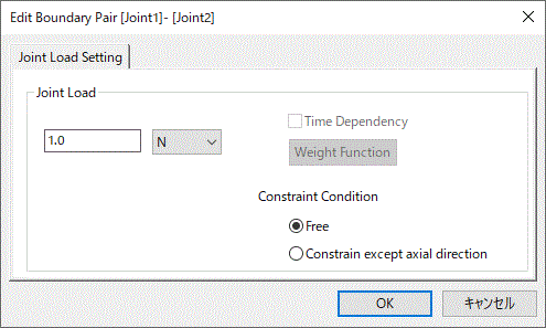
To have the effective load between the two joint load boundaries, the load value must be set.
To pair the joint load boundaries, proceed as follows.
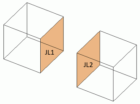
It is assumed that the joint load conditions JL1 and LJ2 are set to the different topologies.
Spring Boundary Pair Setting (Menu)
|
|
|
|

 .
.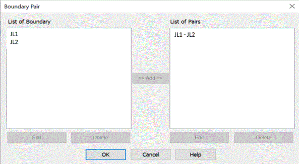
How to Change the Spring Connection Boundary Pair (from Project Tree)
|
|
|
|
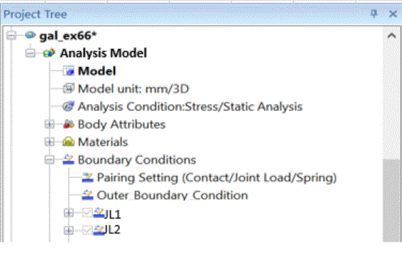
The Boundary Pair Dialog Box Setup
|
Setting Item |
Notes |
||||||||
|
List of Boundary Conditions |
From the boundary conditions registered in the database, the list of those for the boundary pair will appear. Double click one. The [Edit Boundary Condition] dialog box will show up. To remove it from the list, press the [Delete] button. |
||||||||
|
List of Pairs |
The registered pairs will be listed here. Double click one. The [Edit Boundary Pair] dialog box will show up and you can edit the data. (For the joint load, its value can be edited.) To remove it from the list, press the [Delete] button. |
||||||||
|
Add |
Selects the boundary conditions to pair up in the list. By pressing the Add button, the Edit Boundary Pair dialog will show up. The OK button completes the pairing. |
||||||||
|
Delete |
Deletes the boundary conditions from each list. |
||||||||
|
Edit |
Sets the joint load value.
|