Home / How to Set Body Attribute, Material Property and Boundary Condition / Magnetic Analysis [Gauss, Luvens] / Body Attribute / How to Define Loop Coil with Boundary Condition
How to Define Loop Coil with Boundary Condition
Generally, to apply current to loop coil with magnetic field 3D analysis, select [Loop Coil/Magnetic Field Direction] in [Direction] on [Current tab].
Here is another method in case analysis is not performed properly (current is not applied properly, etc).
Although it takes time to define the loop coil, there will be higher possibility of successful analysis.
This method is available only for the static analysis and harmonic analysis.
Define the model in the following procedure.
-
Create a loop body.
-
Cut it in half.
-
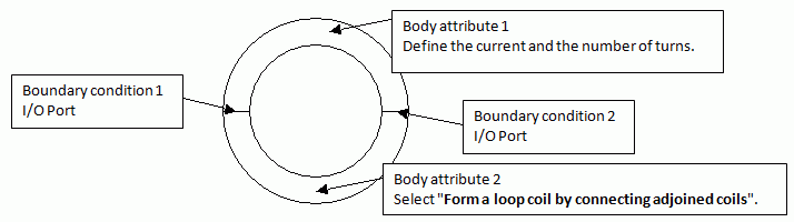
Set the port boundary condition on the two sections.
Assign different names to them.
-
Set a body attribute on either one of the cut loop coils by defining the current and the number of turns on the Current tab, and select [Specify Boundary Conditions]
-
Set another body attribute on the other, and select
[Form a loop coil by connecting adjoined coils].
-
Current direction
The current is to flow in the direction of alphanumerical order of boundary condition names in the body with
the current,and the number of turns defined.
For example, if the boundary condition names are P1 and P2, the current will flow from P1 to P2.
-
It is invalid to have induced current in loop coil.
To do so, create two separate arc coils instead of a single loop coil.
The procedure is as follows.
1. Create a loop body.
2. Cut it at 2 places to make a gap.
3. Subtract the gap from the air by Boolean. The gap will be out of analysis domain.
4. Set the ports on both ends of the loop.
|
|


