|
Home / How to Set Body Attribute, Material Property and Boundary Condition / Body Attribute Tabs / Current Tab
Current Tab
The current for the body is set on this tab.
It is used for the magnetic analysis.
It is shown in the [Edit Body Attribute] dialog box. See [How to Set Body Attribute/Material Property].
|
Setting Item |
Notes |
|
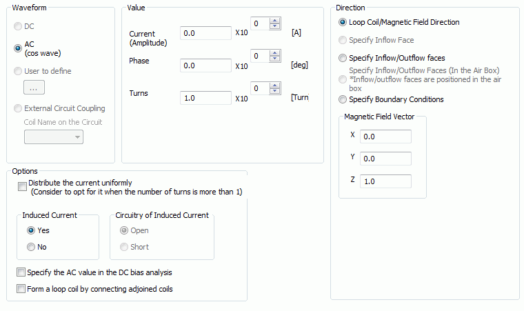
Waveform |
Sets the type of waveform.
Constant: Selectable for the constant current.
AC (cos wave): Selectable for the AC. Available in the harmonic analysis and the transient analysis. Current [A] will be as follows. Amplitude *cos(2πf*t+θπ/180)
User to define: Defines any waveform for the current. Available only in the transient analysis. Sets the current for each time in the [Time-Current] table. If the current values of the 1st and last points of the data are the same, the set data is treated as one cycle and repeated. If it is not repeated, fill in the table through the final timestep.
External Circuit Coupling: Enables coupled analysis with an external circuit. Selectable only in the transient analysis.
Coil Name on the Circuit: Sets the names of FEM elements on the external circuit for coupling. If the [Coil Name on the Circuit] is selected for the different body attributes, they will be connected in series in the circuit.
|
|
Value |
Current: Sets the value of the current.
Frequency: Sets the frequency of the current. This can be used in the harmonic analysis and the transient analysis.
Phase: If the magnitude is I and the phase is θ, the current can be represented by: Iz = I * exp(jθ), where j is the imaginary unit. This can be used in the harmonic analysis and the transient analysis.
If the current values of the 1st and last points are the same in the user-defined waveform,
Turns: Sets the number of turns of the coil winding. Depending on the analysis type, the settings will vary as below. Transient Analysis For example, if the same body attribute name is given to two bodies and the turns are 10, the number of element wires is 10 each totaling 20. Static Analysis and Harmonic Analysis For example, if the same body attribute name is given to two bodies of the same area and the turns are 10, the number of element wires for each body is 5 totaling 10. (The element wires are set to each body so as to make the current density equal between the bodies.)
|
|
Direction |
Sets the direction of the current. The setting is different depending on the analysis dimension. 3D analysisLoop Coil/Magnetic Field Direction: Selectable for the loop coil (closed coil). Determines the direction by specifying the magnetic field vector created by the loop coil current.
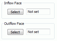
Specify Inflow Face : Determines the current direction if the coil has end faces (not closed coil). Selectable only for rotating machinery in the magnetic transient analysis
Specify Inflow/Outflow Faces Determines the current direction if the coil has end faces (not closed coil).
Specify Inflow/Outflow Faces (In the Air Box): Selectable if the coil has end faces (not closed coil), and inflow/outflow faces exist in the analysis domain. Determines the current direction. Available only in the static analysis. (Analysis can be performed with inflow/outflow faces in the analysis domain)
Specify Boundary Conditions: Determines the direction by setting the port boundary condition on the inflow/outflow faces. Selectable only in the following cases.
2D analysis+Y Direction: Sets the current in the +Y direction.
- Y Direction: Sets the current in the -Y direction.
|
|
Distribute the current uniformly |
If selected, the current distribution going through the coil will be uniform. Otherwise, the current density towards the coil center will be higher. This can be used for the static analysis and the harmonic analysis.
In the case of the lumped coil body representing a multi-turn coil, the current density tends to be higher towards the coil center. This is due to the lumped structure, whereas the actual coil is wound concentrically and the current going through it is supposed to be uniform. In such a case, select this function.
|
|
Induced Current |
Available in the harmonic analysis and the transient analysis.
Yes: Induced current (Eddy current) on the conductor is calculated.
No: Induced current (Eddy current) on the conductor is not calculated.
|
|
Circuitry of Induced Current |
Available in the 2D harmonic and the 2D transient analyses. (Not for axisymmetric analysis)
Open : The circuit will be open if the end of the coil is cut. The sum of the induced current through the cross section of the conductor will be nil.
Short : Selectable if the circuit is not cut at the end (closed circuit conductor). The sum of the induced current through the cross section of the conductor is indefinite.
|
|
Specify the AC value in the superimposed DC analysis |
Specifies the AC value to analyze the superimposed DC characteristic in the harmonic analysis. See [Superimposed DC Characteristic Analysis] for more information.
|
|
Form a loop coil by connecting adjoined coils |
Applied when the 3D analysis failed for a loop coil with [Loop Coil/Magnetic Field Direction]. Refer to [How to Define Loop Coil with Boundary Condition] for details. Available only for the static analysis and harmonic analysis.
|
 Click and select the inflow face in the modeling window.