


|
Home / Examples / Coupled Analysis / Fluid-Thermal Analysis [Bernoulli/Watt] / Example 18: Natural Convection Under Reduced-Pressure Environment
Example 18: Natural Convection Under Reduced-Pressure Environment
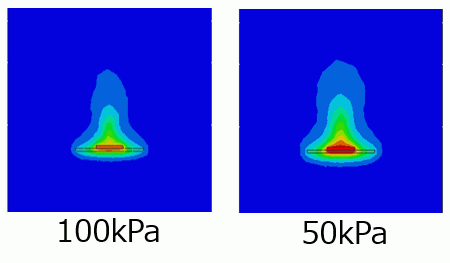
General
-
This is the modified example of Example 6: Cooling of IC by Natural Convection. The same model is solved under a reduced-pressure environment.
-
Compare the heat dissipation characteristics under ambient pressure and reduced pressure.
-
Unless specified in the list below, the default conditions are applied.
-
The above analysis can be performed by modeling a substrate and an IC and applying [Automatic Fluid Creation].
The analysis can also be performed by creating a fluid manually. The setting for the analysis is described at the end of this explanation. -
Obtain this session's project file. (Right-click and choose 'Save link as')
The project has four analysis models.
Ambient temperature and pressure 100 kPa: Analysis with automatic fluid creation
Reduced pressure 50 kPa: Analysis with automatic fluid creation
Ambient temperature and pressure 100 kPa: ic_board_with_air: Analysis with manual fluid creation
Reduced pressure 50 kPa: ic_board_with_air: Analysis with manual fluid creation -
Results will vary depending on Femtet version and the PC environment.
Analysis Space
|
Item |
Settings |
|
Analysis Space |
3D |
|
Model Unit |
mm |
Analysis Conditions
|
Item |
Settings |
|
Solver |
Fluid Analysis [Bernoulli] Thermal Analysis [Watt] |
|
Analysis Type |
Steady-state Analysis |
|
Laminar Flow/Turbulent Flow |
Select Turbulent Flow |
|
Flow Type |
Select [External Flow]. |
|
Ambient Value Setting |
Select [Analyze using the material properties depending on ambient values] Ambient Temperature: 25℃ Ambient Pressure: 51200 Pa (refer to Ambient Value Setting) |
|
Automatic Fluid Creation Setting |
External Flow: Natural convection in the +Z direction |
|
Layer Mesh Setting |
Parameters for Automatic Creation Expected Temperature Difference: 50 [deg] |
|
Detailed Setting |
Deselect [Output main fields only]. |
|
Meshing Setup |
General Mesh Size: 2 [mm] |
Model
The model is a box solid body. The material is Air (000_Air).
Set the inlet/outlet type of the outer boundary condition to natural inflow/outflow.
The substrate (VOL1) and IC (VOL2) are solid bodies.
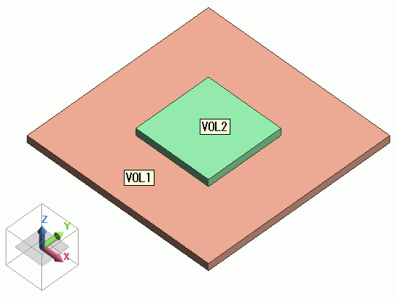
Setting of Body Attributes, Materials, and Mesh Sizes
|
Body Number/Type |
Body Attribute Name |
Material Name |
Mesh Size |
|
0/Solid |
VOL1 |
006_Glass_epoxy * |
- |
|
1/Solid |
VOL2 |
001_Alumina * |
- |
Fluid material 000_Air * is set in the [Automatic Flow Creation] setting.
* Available from the material DB
IC (VOL2) is set as follows on the Heat Quantity tab.
|
Body Attribute Name |
Tab |
Settings |
|
VOL2 |
Heat Quantity |
1W |
Boundary Condition
Set the inlet/outlet type of the outer boundary condition to natural inflow/outflow.
Since the temperature of the incoming fluid is the ambient temperature, the ambient temperature is applied In the [Ambient Setting] dialog box.
Results
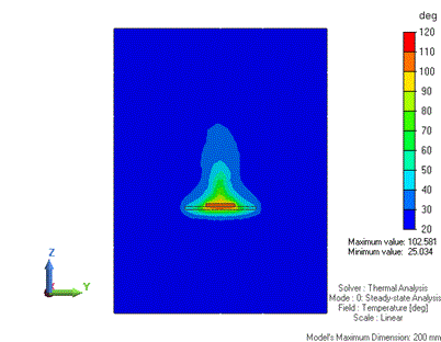
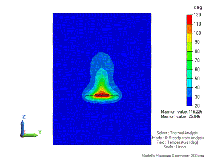
The temperature distribution is shown below.
As in Example 6, the cross section at x = 0 is shown below. The air body is shown as well.
There is a high-temperature area above the IC. You can observe that heat is transferred mainly upward.
It is observed that the IC has higher temperatures under reduced pressure, indicating reduced heat dissipation efficiency.
|
|
|
|
Ambient Pressure (100 kPa) |
Reduced Pressure (50 kPa) |
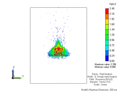
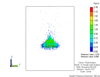
Next, switch the solver type from thermal to fluid analysis to display buoyancy.
The buoyancy under reduced pressure is about half of that under normal pressure.
 |
 |
|
Ambient Pressure (100 kPa) |
Reduced Pressure (50 kPa) |
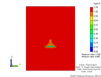
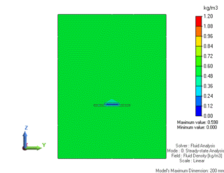
Lastly, the fluid density is shown below.
The density under reduced pressure is about half of that under normal pressure.
This is because the ambient pressure is set to about half of the normal pressure and the density is calculated using it. (refer to Density Tab)
Since buoyancy is calculated using density, the buoyancy under reduced pressure is about half of that under normal pressure. (refer to Section "4 External Force" in Differential Equations in Fluid Analysis/Fluid-Thermal Analysis)
|
|
|
|
Ambient Pressure (100 kPa) |
Reduced Pressure (50 kPa) |
Do not apply [Automatic Fluid Creation]
For reference, the settings for analysis with [Automatic Fluid Creation] disabled are described below.
Analysis Conditions [Manual Fluid Creation]
|
Item |
Settings |
|
Solver |
Fluid Analysis [Bernoulli] Thermal Analysis [Watt] |
|
Analysis Type |
Steady-state Analysis |
|
Laminar Flow/Turbulent Flow |
Select Turbulent Flow |
|
Flow Type |
Select [External Flow]. |
|
Ambient Value Setting |
Select [Analyze using the material properties depending on ambient values] Ambient Temperature: 25℃ Ambient Pressure: 51200 Pa (refer to Ambient Value Setting) |
|
Layer Mesh Setting |
Parameters for Automatic Creation Expected Temperature Difference: 50 [deg] |
|
Detailed Setting |
Deselect [Output main fields only]. |
|
Meshing Setup |
General Mesh Size: 10 [mm] |
Model [Manual Fluid Creation]
The model is a box solid body. The material is Air (000_Air).
Set the inlet/outlet type of the outer boundary condition to natural inflow/outflow.
The substrate (VOL1) and IC (VOL2) are solid bodies.
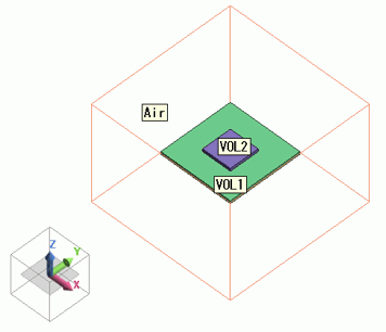
Setting of Body Attributes, Materials, and Mesh Sizes [Manual Fluid Creation]
|
Body Number/Type |
Body Attribute Name |
Material Name |
Mesh Size |
|
0/Solid |
VOL1 |
006_Glass_epoxy * |
2.0 |
|
1/Solid |
VOL2 |
001_Alumina * |
2.0 |
|
2/Solid |
Air |
000_Air * |
- |
* Available from the material DB
IC (VOL2) is set as follows on the Heat Quantity tab.
|
Body Attribute Name |
Tab |
Settings |
|
VOL2 |
Heat Quantity |
1W |
Boundary Condition [Manual Fluid Creation]
|
Boundary Condition Name/Topology |
Tab |
Boundary Condition Type |
Settings |
|
Outer Boundary Condition |
Fluid-Thermal |
Inlet/Outlet |
Natural Inflow/Outflow Inflow Temperature: Use ambient temperature (25 [deg]) |