|
Home / Examples / Coupled Analysis / Fluid-Thermal Analysis [Bernoulli/Watt] / Example 19: Axial Fan
Example 19: Axial Fan
General
-
Create an axial fan model to perform fluid-thermal analysis.
-
Air is fed from the high-temperature domain to the low-temperature domain by a centrifugal fan. The resulting temperature distribution is calculated.
-
The results from constant flow-rate air are shown below.
Analysis model with PQ characteristics set is also included in the project file.
-
The analysis can be performed with other fans of different sizes by changing parameters.
-
Unless specified in the list below, the default conditions are applied.
-
Obtain this session's project file. (Right-click and choose 'Save link as')
-
Results will vary depending on Femtet version and the PC environment.
Analysis Space
|
Item |
Settings |
|
Analysis Space |
3D |
|
Model Unit |
mm |
Analysis Conditions
|
Item |
Settings |
|
Solver |
Fluid Analysis [Bernoulli] Thermal Analysis [Watt] |
|
Analysis Type |
Steady-state Analysis |
|
Laminar Flow/Turbulent Flow |
Select Turbulent Flow |
|
Flow Type |
Select External Flow. |
|
Convergence Judgment by Monitored Value |
Fluid-Thermal Analysis tab: Detailed Settings Select [Convergence Judgment by Monitored Value] Click the [Automatic Monitoring Setting button and then |
Model
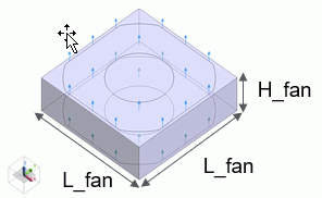
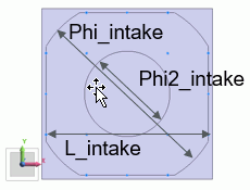
A rectangular solid body is created. A shape of intake/exhaust is imprinted on the surface, and an axial fan model is created. (Segment Face (delete Tool) is used among modification operations)
Dimensions are input using the following variables.
By changing the values of variables, the dimensions can be changed.
|
Variable |
Value |
Notes |
|
H_fan |
20 |
Height of fan |
|
L_fan |
60 |
Edge length of fan |
|
L_intake |
L_fan*0.95 |
Edge Length of intake/exhaust |
|
Phi_intake |
L_fan*1.1 |
Outer diameter of intake/exhaust |
|
Phi2_intake |
30 |
Inner diameter of intake/exhaust |
|
t |
1 |
Height of plate |
|
L |
400 |
Edge length of air domain |
|
mesh_fan |
L_fan/10 |
Mesh size of fan |
Hollow out the intake/exhaust shape from a plate with a thickness of t and an edge length of L to create the plate body.
Create an air body with an edge length of L such as it covers the whole fan model.
The air body is divided into upper and lower bodies in order to change the temperature of the air inflowing from the lower domain beneath the plate body.
Set the boundary condition [Hot_Inlet] to the surfaces of the lower air body.
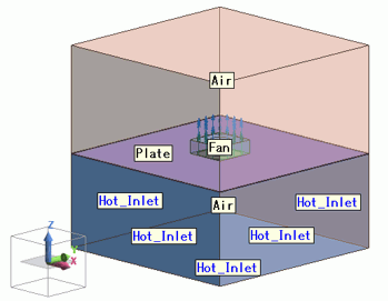
Setting of Body Attributes, Materials, and Mesh Sizes
|
Body Number/Type |
Body Attribute Name |
Material Name |
Mesh Size |
|
0/Solid |
Fan |
002_Polycarbonate(PC) * |
mesh_fan(L_fan/10) |
|
12/Solid |
Plate |
001_Al * |
mesh_fan(L_fan/10 |
|
13/Solid |
Air |
000_Air * |
- |
|
14/Solid |
Air |
000_Air * |
- |
* Available from the material DB
The body Fan is set up on the fluid tab as follows.
|
Body Attribute Name |
Tab |
Settings |
|
Fan |
Fluid |
Fluid Body Type: Specify flow Select inflow face (intake) and outflow face (exhaust) in the model. Inlet/Outlet Type: Specify flow rate 0.7 [m3/min] |
Boundary Conditions
|
Boundary Condition Name/Topology |
Tab |
Boundary Condition Type |
Settings |
|
Hot_Inlet |
Fluid-Thermal |
Inlet/Outlet |
Natural Inflow/Outflow Fluid Temperature: Direct Entry 30[ deg] |
Set the inlet/outlet type of the outer boundary condition to natural inflow/outflow.
Since the temperature of the incoming fluid is the ambient temperature, the ambient temperature is applied In the [Ambient Setting] dialog box.
Results
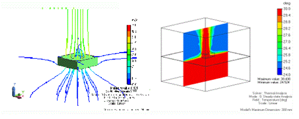
Select intake and exhaust faces and display streamlines as shown below.
It is observed that air is drawn in from the surrounding lower domain and exhausted vertically from the fan into the upper domain.
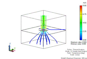
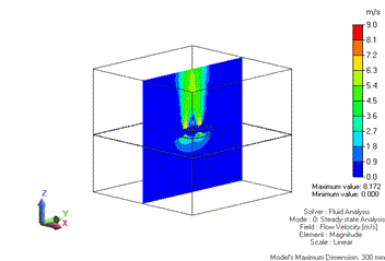
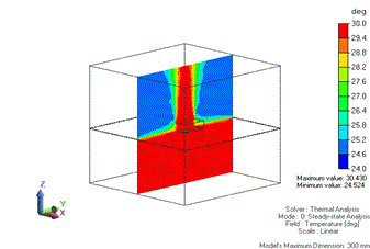
Contour diagrams of flow velocity and temperature distributions at the cross section (x=0) are shown.
You can observe that a high-temperature fluid is exhausted upward.