


|
Home / Examples / Fluid Analysis [Bernoulli] / Example 17: Solder Wicking Analysis
Example 17: Solder Wicking Analysis
General
-
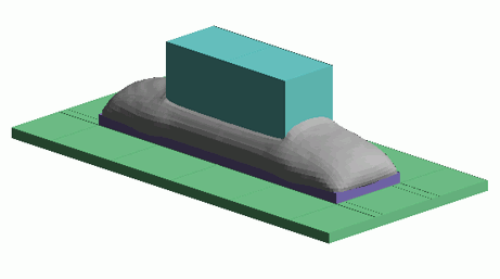
The shape of the solder bridging the terminal and copper foil is analyzed using the VOF method.
-
The volume fractions of soler and air each are solved.
-
Unless specified in the list below, the default conditions are applied.
-
2D and 3D analysis models are provided.
-
Simulation Time (2D): around 16 minutes
Simulation Time (3D): around 32 minutes
-
Obtain this session's project file. (Right-click and choose 'Save link as')
-
Results will vary depending on Femtet version and the PC environment.
Analysis Space
|
Item |
Settings |
|
Analysis Space |
2D |
|
Model Unit |
mm |
Analysis Conditions
|
Item |
Tab |
Settings |
||||||||
|
Solver |
Solver Selection |
Fluid Analysis [Bernoulli] |
||||||||
|
Analysis Type |
Fluid Analysis |
Transient Analysis |
||||||||
|
Free Surface Analysis (VOF Method) |
Fluid Analysis |
Free Surface Analysis (VOF Method): Select |
||||||||
|
Free Surface Analysis (VOF Method) Setting |
Fluid Analysis |
Phase Setting: Register [000_Air] and [LiquidSolder]
The material [LiquidSolder] needs to be registered beforehand.
Take into account weight: Select Take into account surface tension: Select Phase Pair Setting:
|
||||||||
|
Setup Details |
Fluid Analysis Setup Details |
Volume Control Type: Cell-centered Base |
||||||||
|
Timestep |
Transient Analysis |
|
||||||||
|
Meshing Setup (2D Analysis) |
Mesh |
|
||||||||
|
|
|
|||||||||
|
Meshing Setup (3D Analysis) |
Mesh |
|
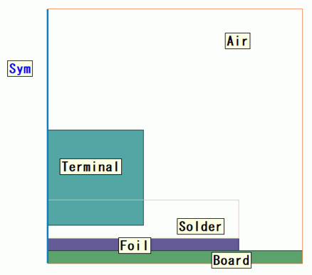
Model (2D Analysis)
Model (3D Analysis)
Divide the body beforehand such that meshes are created regularly with hexahedral mesh by sweep mesh.
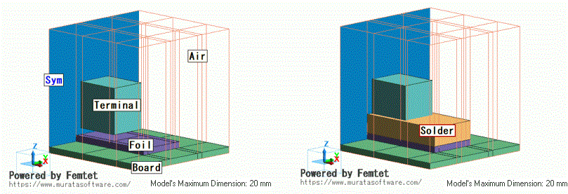
Body Attributes and Materials
|
Body Number/Type |
Body Attribute Name |
Material Name |
|
0/Face |
Air |
000_Air * |
|
1/Face |
Board |
006_Glass_epoxy * |
|
2/Face |
Foil |
008_Cu * |
|
3/Face |
Terminal |
008_Cu * |
|
4/Face |
Solder |
LiquidSolder |
* Available from the material DB
The material property of LiquidAir is set as follows. For a stable calculation of the steady state, a high viscosity value is set.
|
Material Name |
Tab |
Settings |
|
LiquidSolder |
Solid/Fluid |
Liquid |
|
|
Density |
7400 [kg/m3] |
|
|
Viscosity |
400 x 10^-3 [Pa s] |
The contact angle is set in the body attributes of Board.
|
Body Attribute Name |
Tab |
Settings |
||||||
|
Board |
Solid |
Multiphase Flow Setting (Contact Angle Setting): Specify for each body attribute: Select Phase Pair Setting:
|
Boundary Condition
|
Boundary Condition Name/Topology |
Tab |
Boundary Condition Type |
Settings |
|
Sym/Edge |
Symmetry/Continuity |
Symmetry(*) |
Select [Symmetric Face] |
|
Outer Boundary Condition |
Fluid |
Inlet/Outlet |
Natural Inflow/ Natural Outflow |
Results
The volume fraction contours of phase 2 at 0 [s], 0.01 [s], 0.03 [s], and 0.04 [s] are shown below.
The part of phase 2 (LiquidSolder) is illustrated in red.
The results at 0.03 [s] and 0.04 [s] are similar. They show the solder shape in equilibrium.
| 0.0 [s] | 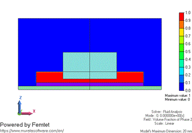 |
| 0.01 [s] | 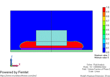 |
| 0.02 [s] | 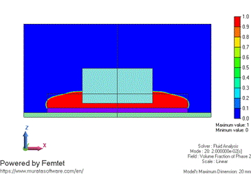 |
| 0.03 [s] | 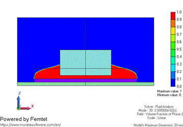 |
| 0.04 [s] | 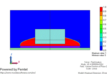 |
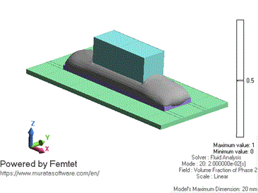
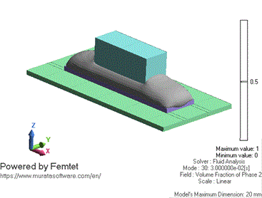
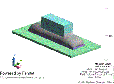
The results of the 3D analysis are shown below.
The contour on the cross section and the isosurface contour are shown below. The surface of 0.5 is the boundary between solder and air.
The isosurface contour is displayed in gray.
| 0.0 [s] | 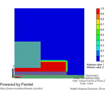 |
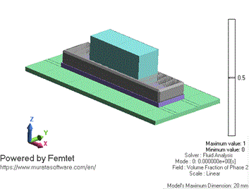 |
| 0.01 [s] | 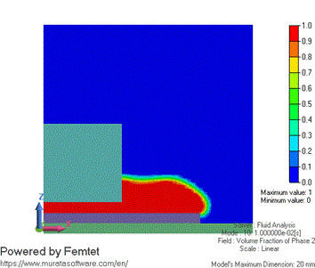 |
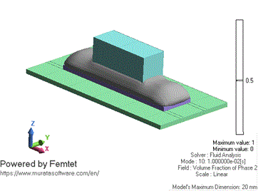 |
| 0.02 [s] | 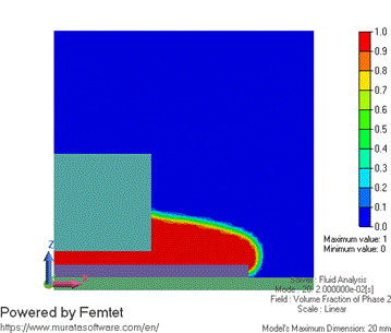 |
 |
| 0.03 [s] | 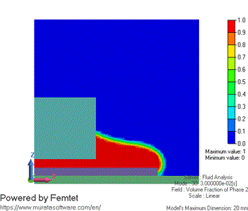 |
 |
| 0.04 [s] | 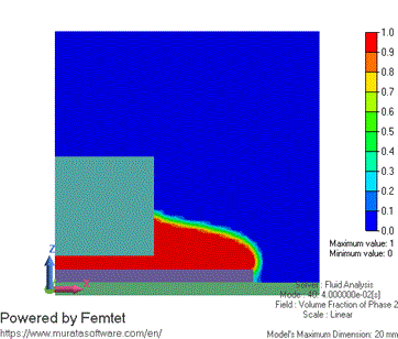 |
 |