


|
Home / Examples / Coupled Analysis / Electric-Thermal-Stress Analysis [Coulomb/Watt/Galileo] / Example 1: Deformation of Conductive Strip due to Heating
Example 1: Deformation of Conductive Strip due to Heating
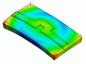
General
-
The model is a strip line having bend shapes. An electric potential is given across the strip line and the electric current is solved in the electric analysis.
Then the eventual joule loss and temperature rise are solved in the thermal analysis.
Then the deformation caused by the temperature rise is solved in the stress analysis.
-
After executing Example 2 of the electric-thermal analysis, stress analysis (Galileo) is executed.
-
Unless specified in the list below, the default conditions will be applied.
-
Obtain this session's project file. (Right-click and choose 'Save link as')
-
Results will vary depending on Femtet version and the PC environment.
Analysis Space
|
Item |
Settings |
|
Analysis Space |
3D |
|
Model Unit |
mm |
Analysis Conditions
Solvers used are Coulomb, Watt, and Galileo.
|
Item |
Settings |
|
Solver |
Electric Analysis [Coulomb] Thermal Analysis [Watt] Stress Analysis [Galileo] |
|
Analysis Type (Coulomb/Watt) |
Steady-state Analysis |
|
Options |
N/A * |
* [Thermal Load] is selected by default for the thermal-stress coupled analysis.
The reference temperature is set on the Step/Thermal Load tab.
|
Tab |
Setting Item |
Settings |
|
Step/Thermal Load |
Reference Temperature |
25 [deg] |
* The reached temperatures come from the thermal analysis.
Model
The same as the example 2 of electric-thermal coupled analysis.
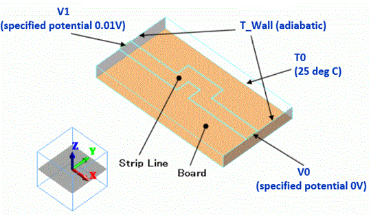
Body Attributes and Materials
|
Body Number/Type |
Body Attribute Name |
Material Name |
|
0/Solid |
Board |
001_Alumina * |
|
6/Solid |
Strip |
008_Cu * |
* Available from the material DB
It is assumed that there is no current flow in the alumina substrate.
|
Body Attribute Name |
Thickness/Width |
Analysis Domain |
|
Board |
|
Solver: Deselect Electric Analysis (Coulomb) |
Resistivity/conductivity is required to be set to “Board” to run the Coulomb/Watt solver
even though it is not used in the electric analysis. As the resistivity in the database of the 001_Alumina is not defined by default,
the value is temporarily set to 1.0. (The result will not be affected)
In the thermal analysis, specific heat is required. It is not defined in the database of the 001_Alumina either.
Therefore the setting below is applied.
|
Material Name |
Specific Heat |
Resistivity |
|
001_Alumina |
1.0 [J/kg/deg] |
1.0 [Ωm] |
Boundary Conditions
-
The temperature of the bottom face of the substrate is set to 25 [deg] using the boundary condition of T0.
-
The [Adiabatic] boundary condition is set to a part of faces using the boundary condition of T_Wall.
This keeps the outer boundary condition from being applied on those faces. -
Boundary conditions, V0 and V1, define the electric potential at each end of the microstrip line.
-
The heat transfer to the ambient is defined by the outer boundary condition.
-
It is not fixed mechanically.
|
Boundary Condition Name/Topology |
Tab |
Boundary Condition Type |
Settings |
|
T_Wall/Face |
Thermal |
Adiabatic |
|
|
T0/Face |
Thermal |
Temperature |
25 [deg] |
|
V0/Face |
Electric |
Electric Wall |
Electric Potential Specified, Waveform: Constant, Electric Potential: 0.00 V |
|
V1/Face |
Electric |
Electric Wall |
Electric Potential Specified, Waveform: Constant, Electric Potential: 0.01 V |
|
Outer Boundary Condition * |
Thermal |
Heat Transfer/Convection |
Coefficient of Heat Transfer: 10 [W/m2/deg] Ambient Temperature: 25 [deg] |
To set Outer Boundary Condition, go to the [Model] tab
and click [Outer Boundary Condition]  .
.
Results
See Example 3 of electric-thermal coupled analysis for the temperature distribution.
The deformation as a result of stress analysis is shown below. The vectors represent the stresses. The unit is [Pa].
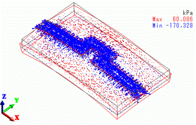
The strip line rises in temperature and expands, causing the substrate to bend.