


|
Home / Examples / Electric Analysis [Coulomb] / Example 3: Capacitances across Multiple Electrodes
Example 3: Capacitances across Multiple Electrodes
General
-
In Example 1, the capacitor with two parallel conductive plates which have the electric potential difference was analyzed.
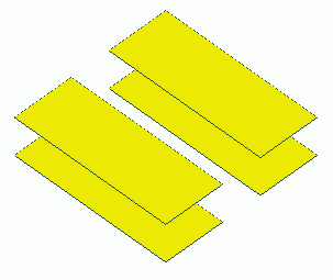
The model consists of two pair of two parallel conductive plates which have an electric potential difference.
-
The capacitances across the electrodes, the electric field, and the equipotential map are solved.
-
Unless specified in the list below, the default conditions will be applied.
-
Obtain this session's project file. (Right-click and choose 'Save link as')
-
Results will vary depending on Femtet version and the PC environment.
Analysis Space
|
Item |
Settings |
|
Analysis Space |
3D |
|
Model Unit |
mm |
Analysis Conditions
Select [Static analysis] as the electric potential is static.
|
Item |
Settings |
|
Solver |
Electric Analysis [Coulomb] |
|
Analysis Type |
Static Analysis (Capacitance) |
|
Options |
N/A |
The electric field exists outside the analysis domain. Therefore the open boundary condition below is applied initially.
|
Tab |
Setting Item |
Settings |
|
Open Boundary Tab |
Type |
Absorbing Boundary |
|
Order of Absorbing Boundary |
1st-order |
Model
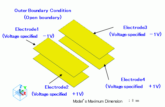
Create 4 sheet bodies for electrodes. Then, specify the voltage on each as boundary condition.
Body Attributes and Materials
Four sheet bodies are used to imprint the electric potential-specified boundary condition.
They are called "imprinting body".
You don't need to set the body attribute or the material property on them.
|
Body Number/Type |
Body Attribute Name |
Material Name |
|
1/Sheet |
Imprinting body |
|
|
2/Sheet |
Imprinting body |
|
|
3/Sheet |
Imprinting body |
|
|
4/Sheet |
Imprinting body |
|
* Available from the material DB
Boundary Conditions
|
Boundary Condition Name/Topology |
Tab |
Boundary Condition Type |
Settings |
|
Electrode1/Face |
Electric |
Electric Wall |
Electric Potential Specified -1 [V] |
|
Electrode2/Face |
Electric |
Electric Wall |
Electric Potential Specified +1 [V] |
|
Electrode3/Face |
Electric |
Electric Wall |
Electric Potential Specified -1 [V] |
|
Electrode4/Face |
Electric |
Electric Wall |
Electric Potential Specified +1 [V] |
|
Outer Boundary Condition * |
Electric |
Open Boundary |
|
To set Outer boundary condition, go to the [Model] tab
and click [Outer Boundary Condition]  .
.
Results
To view the calculation results, go to the [Results] tab

and click [Show Numerical Summary Table]  .
.
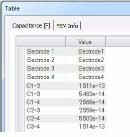
The capacitances across Electrode1 and Electrode2 and across Electrode and Electrode4 are higher than others
The vectors of the electric field are shown below.
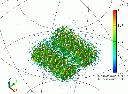
The electric field is generated between two electrodes.
The gradation contour of the electric potential on the YZ section is shown below.
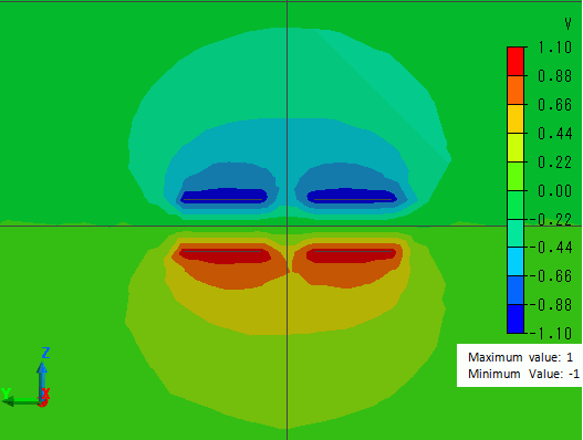
You can visually grasp the distributed electric potential in the space around the electrodes.