


|
Home / Examples / Electric Analysis [Coulomb] / Example 5: Electric Field Created by Point Charge
Example 5: Electric Field Created by Point Charge
General
-
In this example, a point charge is placed in the air.
-
The electric field created by it is solved and the equipotential map is acquired.
-
Unless specified in the list below, the default conditions will be applied.
-
Obtain this session's project file. (Right-click and choose 'Save link as')
-
Results will vary depending on Femtet version and the PC environment.
Analysis Space
|
Item |
Settings |
|
Analysis Space |
3D |
|
Model Unit |
mm |
Analysis Conditions
Select "Static analysis" as the electric potential is static.
|
Item |
Settings |
|
Solver |
Electric Analysis [Coulomb] |
|
Analysis Type |
Static Analysis (Capacitance) |
|
Options |
N/A |
In actuality, the electric field exists outside the analysis domain. Therefore the open boundary condition below is applied initially.
|
Tab |
Setting Item |
Settings |
|
Open Boundary Tab |
Type |
Absorbing boundary |
|
Order of Absorbing Boundary |
1st-order |
As air domain cannot be created automatically for this model, automatic creation is deselected.
(There are vertex bodies only. Air domain size is not fixed automatically.)
|
Tab |
Setting Item |
Settings |
|
Mesh Tab |
Air Domain Creation |
Create air domain automatically: Deselect |
Model
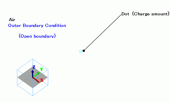
A solid body represents the air. A vertex body placed in the center of the air represents the point charge.
Body Attributes and Materials
The vertex body is used to set the point charge in the body attribute.
Assign a material to it even though the material property does not affect the simulation.
|
Body Number/Type |
Body Attribute Name |
Material Name |
|
0/Solid |
Air |
000_Air(*) |
|
1/Vertex |
Dot |
000_Air(*) |
* Available from the material DB
Point charge is set in the body attribute.
|
Body Attribute Name |
Charge |
|
Dot |
Electric Charge: Electric Charge 1x10-12 [C] |
Boundary Conditions
|
Boundary Condition Name/Topology |
Tab |
Boundary Condition Type |
Settings |
|
Outer Boundary Condition * |
Electric |
Open Boundary |
|
To set Outer Boundary Condition, go to the [Model] tab
and click [Outer Boundary Condition]  .
.
Results
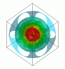
The isosurface contour of the electric potential is shown below.
At Minimum/Maximum Values on the Contour tab of [Graphics Setup], deselect [Automatic] and set 0.5 => 5.0.
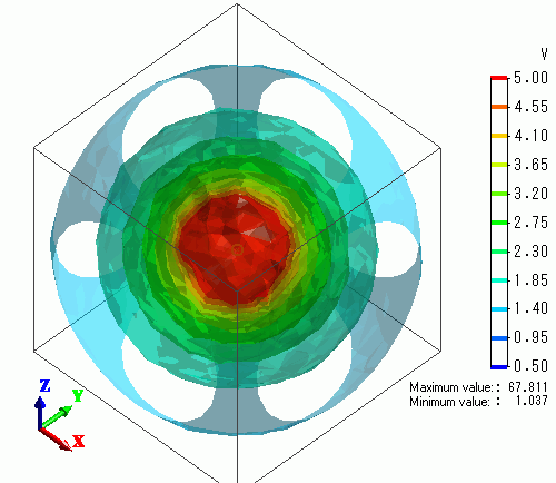
The figure shows the equipotential map.