


|
Home / Examples / Stress Analysis [Galileo] / Example 6: Deformation of Spring Plate
Example 6: Deformation of Spring Plate
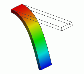
General
-
The deformation of a spring plate under forced displacement is analyzed.
-
If an object is deformed beyond the limit of its elasticity, the large deformation occurs. It is treated as a nonlinear problem.
See Technical Note Analysis of Large Deformation (Geometric Nonlinearity).
-
The distributions of displacement and stress are solved.
-
Unless specified in the list below, the default conditions will be applied.
-
Obtain this session's project file. (Right-click and choose 'Save link as')
-
Results will vary depending on Femtet version and the PC environment.
Analysis Space
|
Item |
Settings |
|
Analysis Space |
3D |
|
Model Unit |
m |
Analysis Conditions
To solve the deformation caused by static load, the static analysis is selected.
As the element has rotation and large strain involved, [Large Displacement] option needs to be selected as well.
This will activate Galileo's nonlinear solver.
|
Item |
Settings |
|
Solver |
Stress Analysis [Galileo] |
|
Analysis Type |
Static Analysis |
|
Large Deformation |
Select [Large Displacement]. |
Model
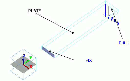
The spring plate is a rectangular solid body. The material is polycarbonate.
The plate is mechanically fixed at one end.
The forced displacement is applied on the other end.
Body Attributes and Materials
|
Body Number/Type |
Body Attribute Name |
Material Name |
|
0/Solid |
PLATE |
000_Polyethylene(PE) * |
* Available from the material DB
Boundary Conditions
|
Boundary Condition Name/Topology |
Tab |
Boundary Condition Type |
Settings |
|
FIX/Face |
Mechanical |
Displacement |
Select all X/Y/Z components. UX=0, UY=0, UZ=0 |
|
PULL/Edge |
Mechanical |
Displacement |
Select the Z component. Z = -15 [m] |
Results
The simulation is divided in 20 substeps. Calculate each step with a gradually larger displacement.
20 results are output for the steps between 0.05 [Step] and 1 [Step].
The number of substeps is 20 by default. It can be adjusted on the Step/Thermal Load tab.
All the results of substeps are output by default. Only the final result of 1 [Step] can be output.
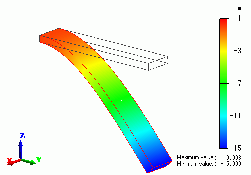
The contour diagram shows the Z displacement at 1 [Step].
The scale adjustment ratio on the Displacement tab of the Graphics Setup is set to 1.
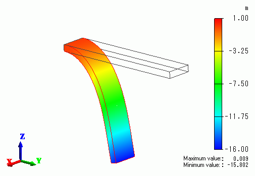
The tip of the plate is curling towards -Y direction.
If [Show all results summary] is selected, the external force and reactive force are listed in the table below.
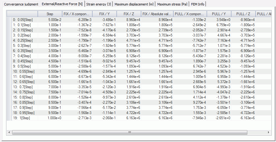
The reactive force at the boundary condition FIX is a total of 6.163e+6 [N] in + Z direction at 1 [Step].
The external force at PULL is a total of 6.163e+6 [N] in -Z direction at 1 [Step].
For comparison, the displacement without Large Displacement is calculated and the result is shown below.
The tip is not curving back downward towards the root. That is unnatural.