


|
Home / Examples / Stress Analysis [Galileo] / Example 33: Analysis of an Fallen Object
Example 33: Analysis of an Fallen Object
General
-
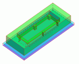
An object consisting of a substrate and a frame falls onto the floor and bounces off. The transient analysis is performed.
-
The deformation, the displacement distribution, and the stress distribution are solved.
-
Unless specified in the list below, the default conditions will be applied.
-
Obtain this session's project file. (Right-click and choose 'Save link as')
-
Results will vary depending on Femtet version and the PC environment.
-
The stress transient analysis is available in an optional package.
Analysis Space
|
Item |
Settings |
|
Analysis Space |
3D |
|
Model Unit |
mm |
Analysis Conditions
|
Item |
Settings |
|
Solver |
Stress analysis [Galileo] |
|
Analysis Type |
Transient Analysis |
|
Large deformation |
Large Displacement |
|
Options |
Select [Acceleration]. |
The acceleration, the transient analysis, and the high-level setting tabs are set up as follows .
|
Tab |
Setting Item |
Settings |
|
Acceleration |
Acceleration |
(X,Y,Z) = (0, 0, -9.8) [m/s2] |
|
Transient analysis |
Timestep |
0.0005 [sec] |
|
Number of Calculation Steps |
20 |
|
|
Output Interval |
1 |
Model
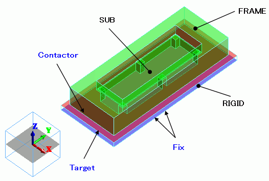
The object falls from the height of 1.5 [m].
The calculation begins when the object is positioned 0.001 [m] above the floor, with an initial velocity of -5.420369 [m/s].
The frame and the substrate are solid bodies. The floor is a rigid body.
Body Attributes and Materials
|
Body Number/Type |
Body Attribute Name |
Mesh Size |
Material Name |
|
9/Solid |
FRAME |
10 |
001_Al * |
|
10/Solid |
SUB |
5 |
008_Cu * |
|
11/Solid |
RIGID |
|
Rigid |
* Available from the Material DB
Material property of the rigid body is set up as follows.
|
Material Name |
Tab |
Settings |
|
Rigid |
Elasticity |
Young's Modulus: 1.0e20 [Pa] Poisson's Ratio: 0.0 |
|
Density |
1000 [kg/m3] |
Initial velocities are set in the body attributes.
|
Body Attribute Name |
Tab |
Settings |
|
FRAME |
Initial Velocity |
(X,Y,Z) = (0, 0, -5.420369) [m/s] |
|
SUB |
Initial Velocity |
(X,Y,Z) = (0, 0, -5.420369)[m/s] |
Boundary Conditions
The bottom face of the frame makes a contact with the top face of the rigid floor.
The displacement of the rigid floor is set to zero, because it is fully fixed.
|
Boundary Condition Name/Topology |
Tab |
Boundary Condition Type |
Settings |
|
Contactor/Face |
Mechanical |
Contact Surface |
Contact Surface Classification: Contactor Surface |
|
Target/Face |
Mechanical |
Contact surface |
Contact Surface Classification: Contactee Surface |
|
Fix/Face |
Mechanical |
Displacement |
Select UX, UY, and UZ all. Set all components to zero. |
* After setting the contact surface, go to the [Model] tab,
and click [Boundary Pair]  . Pair "Contactor" and "Target" in the Boundary Pair dialog box.
Results
The general mesh size is set to 14.
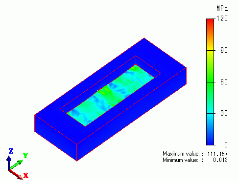
The contour diagrams below show von Mises equivalent stress. Note that [Set Emphasizing Scale] is set to 10 on the Displacement Diagram tab of [Graphics Setup].
The rigid body is hidden.
The moment of the collision (t = 0.0002 [sec])
0.0001 sec after the collision (t = 0.0003 [sec])
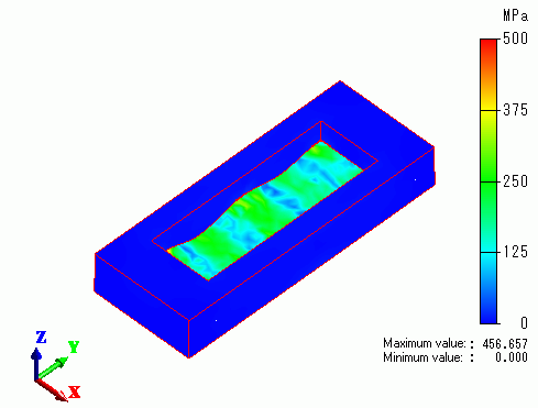
0.0003 sec after the collision (t = 0.0005 [sec])
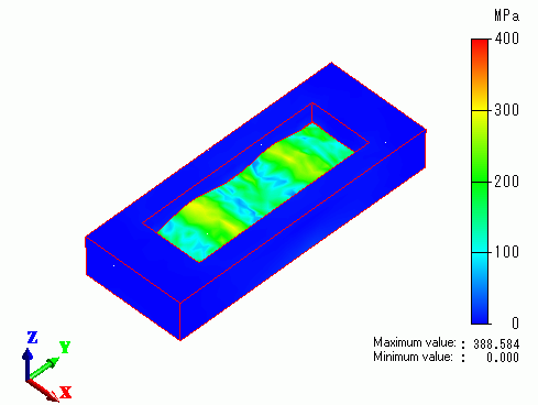
These diagrams show that the substrate deforms as time passes since the collision.