|
Home / Examples / Stress Analysis [Galileo] / Example 58: Spring Back Analysis with ON/OFF Setting
Example 58: Spring Back Analysis with ON/OFF Setting
General
-
Analysis is performed on a plate which is bent in 90° angle and then released.
-
Procedure for the release after the 90° bent is set by applying [ON/OFF] setting of the boundary condition.
-
Alternatively, the same results will be given by selecting [Add unloading step] with the step setting of [Single-step].
(The analysis model with the unloading setup is also included in the project file)
-
The elasto-plastic material is used. The plastic deformation will take place at the bending and the material will go backward to the original position in a small degree after the release.
(This nature is called spring back)
-
Unless specified in the list below, the default conditions will be applied.
-
Obtain this session's project file. (Right-click and choose 'Save link as')
-
Results will vary depending on Femtet version and the PC environment.
-
Elasto-plastic analysis is available in an optional package.
Analysis Space
|
Item |
Settings |
|
Analysis Space |
2D |
|
Model Unit |
mm |
Analysis Conditions
Select [Large displacement] in the Large Deformation as deformation of 90° is large.
|
Item |
Settings |
|
Solver |
Stress Analysis [Galileo] |
|
Analysis Type |
Static Analysis |
|
Large Deformation |
Select [Large Displacement] |
Set up as follows on the Step/Thermal Load tab.
Step 1 corresponds to Bend 90°, and Step 2 corresponds to Release (set off the constrain of rotational displacement).
|
Tab |
Setting Item |
Settings |
|||||
|
Step/Thermal Load |
Step Setting |
Multiple Steps |
|||||
|
Step/Reached Temperature Setting |
|
||||||
|
Options for the Multi-Step Analysis |
Select [Save the results of substeps] |
The setting below is done on the High-level setting tab.
[Adjust acceleration/deceleration coefficient automatically] is not selected for this model to have faster calculation.
|
Tab |
Item |
|
High-Level Setting |
Nonlinear Analysis Deselect [Adjust acceleration/deceleration factor automatically] |
Graphical Objects
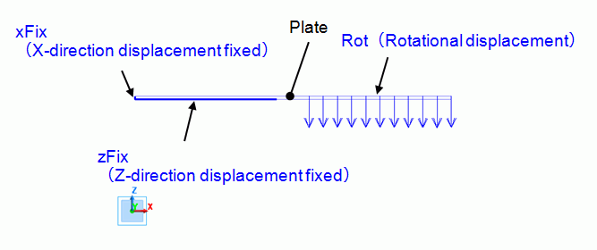
The model is a box solid body with an edge length of 200 mm. The material is elasto-plastic.
Fix the left end in the X direction. Fix the 90mm area of the left end at its bottom in the Z direction.
The plate is bent at its center in 90-degree angle. Set the rotational displacement on the 90mm area of the right end at its top side.
Set the general mesh size at 1.
Body Attributes and Materials
|
Body Number/Type |
Body Attribute Name |
Material Name |
|
0/Solid |
PLATE |
PlasticMat |
|
1,2/Face |
No Setup *1 |
No Setup *1 |
*1 Imprinting body for the boundary condition.
|
Material Name |
Tab |
Properties |
|
PlasticMat |
Elasticity |
Material Type: Elasto-plastic Bilinear Material Property: Young's Modulus: 200x109 [Pa] Poisson's Ratio: 0.3 Strain Hardening Rate: 20x109 [Pa] Initial Yield Stress: 200x106 [Pa] |
Boundary Conditions
Rotational displacement and ON/OFF are set.
|
Boundary Condition Name/Topology |
Tab |
Boundary Condition Type |
Settings |
||||
|
xFix/Face |
Mechanical |
Displacement |
Select the X component. |
||||
|
zFix/Face |
Mechanical |
Displacement |
Select the Z Component. |
||||
|
Rot/Face |
Mechanical |
Rotational Displacement |
Coordinates on Axis: Vectors of Axis Rotation Angles |
||||
|
Set ON/OFF |
Select |
||||||
|
ON/OFF List |
Boundary Condition ON/OFF Tab
*1 |
*1) If [Weight function] tab is selected in the Time/Step Table of ON/OFF List, the loads at the substeps can be viewed.
The figure below is the view when [Show with actual loads] is selected.
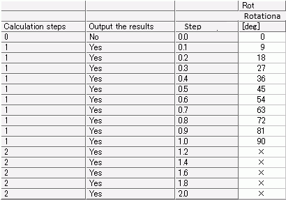
The set rotational displacement will gradually reach to 90[deg] in one step.
It goes up by 4.5[deg] per substep as the number of substeps is 10.
Since OFF (No) is set on the step 2, the constrain of rotational displacement is removed from the first substep in the step 2 onward.
See [Weight Function Setting] for the details of viewing the weight function.
Results
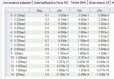
The results of all torques are shown in the table.
The data in the table are shown in the chart below.
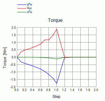
Torque on the boundary Rot is increasing through step 1.
It goes down to zero at the first substep of step 2 (1.2[Step]).
Right after removing the constrain, minute value is observed because the convergence judgment is a bit inaccurate.
But from the following substep onward, the torque is almost zero.
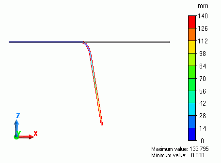
The displacement at the 1st step is shown below. The contour diagram shows the magnitude of displacement.
The 90-degree bending is observed.
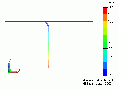
The displacement at the 2nd step is shown below.
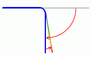
The bending angle is smaller than the step 1 because the constrain of rotational displacement is removed.
Spring back can be observed.