|
Home / Examples / Electromagnetic Analysis [Hertz] / Example 32: Murata's MAGICSTRAP®
Example 32: Murata's MAGICSTRAP®
General
-
The data is available from Murata's web site.
-
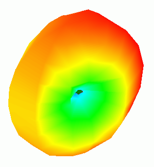
The directivity of MAGICSTRAP® is solved.
-
Obtain this session's project file. (Right-click and choose 'Save link as')
-
Results will vary depending on Femtet version and the PC environment.
Analysis Space
|
Item |
Settings |
|
Analysis Space |
3D |
|
Model Unit |
mm |
Analysis Conditions
|
Item |
Settings |
|
Solver |
Electromagnetic Analysis [Hertz] |
|
Analysis Type |
Harmonic Analysis |
Harmonic Analysis tab and Open Boundary tab are set as follows.
|
Tab |
Setting Item |
Settings |
|
Mesh |
Element Type |
2nd-order Element |
|
Adaptive Meshing |
Select [Apply adaptive meshing]. |
|
|
Frequency-Dependent Meshing |
Reference Frequency: 9.1x10⁸ [Hz] Select [The conductor bodies thicker than the skin depth constitute the boundary condition]. |
|
|
Harmonic Analysis |
Sweep Type |
Select [Linear Step by Frequency] |
|
Sweep Values |
Minimum: 0.7x10⁹ [Hz] Maximum: 1.2x10⁹ [Hz] Frequency Step: 1.0x10⁶ [Hz] |
|
|
Sweep Setting |
Select Fast sweep S-parameter Tolerance: 1x10⁻³ |
|
|
Input |
1.0 [W] |
|
|
Open Boundary |
Type |
Absorbing Boundary |
|
Order of Absorbing Boundary |
1st-order |
Graphical Objects
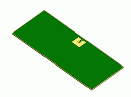
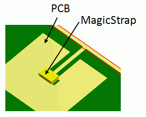
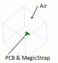
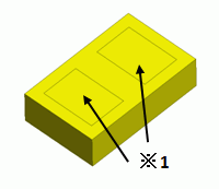
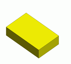
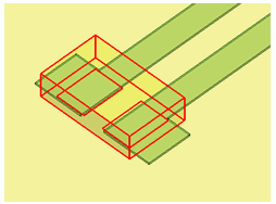
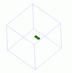
A piece of MAGICSTRAP® is placed on a substrate. They are enclosed in an air cube.
The ports are set inside the device, so they are invisible.
| Whole Model | Zoomed in | MAGICSTRAP® |
|
|
 |
|
Model Creation
|
|
|
 |
|
 |
|
 |
|
 |
Body Attributes and Materials
|
Body Number/Type |
Body Attribute Name |
Material Name |
|
1/Solid |
PCB |
008_Cu *2 |
|
2/Solid |
PCB |
006_Glass_epoxy *2 |
|
3/Solid |
Air |
000_Air(*2) |
|
4/Solid |
MagicStrap |
MagicStrap *1 |
*1 Imported from Murata's CAE data
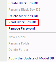
The body attributes and material properties related to the inductor will be replaced by the black box data when the solver runs. Therefore the settings here are irrelevant.
*2 Available from the material DB.
Boundary Conditions
The ports are set inside the device, so they are invisible. The impedance of the IC is set on the ports even though it is not visible.
|
Boundary Condition Name/Topology |
Tab |
Boundary Condition Type |
Settings |
|
Outer Boundary Condition |
Electric |
Open Boundary |
|
Results
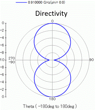
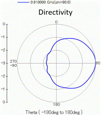
The radiation pattern of MAGICSTRAP® at 910 MHz is plotted with polar graph.
The unit is [dB].
φ=0 [deg], θ=0 to 360 [deg] in 60 steps φ=90 [deg], θ=0 to 360 [deg] in 60 steps
Directivity in 3D