|
Home / Examples / Analysis with Deformed Shape Taken into Account / Example 2: Resistance Change by Deformation
Example 2: Resistance Change by Deformation
General
-
A resistance change of the wire by deformation is analyzed.
-
The principle of strain gauge is simulated in this analysis.
-
[Analysis with deformed shape taken into consideration] is used.
-
Unless specified in the list below, the default conditions will be applied.
-
Obtain this session's project file. (Right-click and choose 'Save link as')
-
Results will vary depending on Femtet version and the PC environment.
Three analysis models are prepared.
・Before deformation (electric analysis)
・Deformed shape calculation (stress analysis)
・After deformation (electric analysis)
See Analysis with deformed shape taken into account for the details.
Analysis Model 1: Before Deformation
Set up the analysis conditions before the deformation. The analysis model is named [Before deformation].
Analysis Space
|
Item |
Settings |
|
Analysis Space |
3D |
|
Model Unit |
mm |
Matrix solver type is iterative method when [Automatic] is selected. But in this example, the direct method is used as the accuracy of the iterative method is low.
|
Tab |
Setting Item |
Settings |
|
High-Level Setting |
Matrix Solver Type |
Direct Method |
Analysis Conditions
|
Item |
Settings |
|
Solver |
Electric Analysis[Coulomb] |
|
Analysis Type |
Static Analysis (Resistance) |
|
Options |
None |
Model
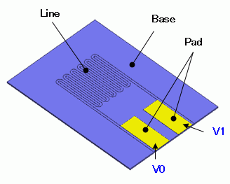
A strain gauge is created.
Create a cubic solid body for a base.
Create a geometry for the line shape.
Create a straight line with sheet body and a curve with wire body. The wire body is rotated and stretched in the thickness direction.
Create cubic solid bodies for pads.
Set the electric potential boundary condition on the top of the solid bodies.
Body Attributes and Materials
|
Body Number/Type |
Body Attribute Name |
Material Name |
|
0/Solid |
Base |
Base |
|
26/Solid |
Pad |
010_Ni * |
|
27/Solid |
Pad |
010_Ni * |
|
28/Solid |
Line |
010_Ni * |
* Available from the material DB
The base is excluded from the analysis domain as it is assumed to be an insulator.
|
Body Attribute Name |
Tab |
Settings |
|
Base |
Analysis Domain |
Deselect "For use in electric analysis" |
Boundary Condition
|
Boundary Condition Name/Topology |
Tab |
Boundary Condition Type |
Settings |
|
V0/Face |
Electric |
Electric Wall |
Electric Potential Specified 1 [V] |
|
V1/Face |
Electric |
Electric Wall |
Electric Potential Specified 0 [V] |
Mesh Size Setting
|
Body Number/Type |
Size |
|
0/Solid |
0.05 |
Analysis Model 2: Deformed Shape Calculation
The device created for Analysis Model 1 is placed on a substrate, and the substrate is bent for stress analysis.
Copy Analysis Model 1 (before deformation) and set up as follows. The analysis model is named [Deformed shape calculation].
See [Copy Analysis Model into Project] for the details.
Analysis Conditions
|
Item |
Settings |
|
Solver |
Stress Analysis [Galileo] |
|
Analysis Type |
Static Analysis |
|
Options |
None |
Model
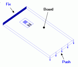
A substrate is created with a cubic solid body and placed under the Analysis Model 1.
Body Attributes and Materials
|
Body Number/Type |
Body Attribute Name |
Material Name |
|
0/Solid |
Base |
Base |
|
26/Solid |
Pad |
010_Ni * |
|
27/Solid |
Pad |
010_Ni * |
|
28/Solid |
Line |
010_Ni * |
|
Body29/Solid |
Board |
006_Glass_epoxy * |
* Available from the material DB
Enter the following value as the Young's modulus of the Base is not defined.
|
Material Name |
Tab |
Settings |
|
Base |
Elastic Modulus |
Young's Modulus: 5.0x10⁹ |
Boundary Condition
Fixation and displacement are given to bend the substrate.
|
Boundary Condition Name/Topology |
Tab |
Boundary Condition Type |
Settings |
|
V0/Face |
Mechanical |
Free |
|
|
V1/Face |
Mechanical |
Free |
|
|
Fix/Face |
Mechanical |
Displacement |
Select all X/Y/Z components. UX=0, UY=0, UZ=0 |
|
Push/Line |
Mechanical |
Displacement |
Select the Z component |
Analysis Model 3: After Deformation
Set up the analysis that takes the deformed shape into account.
Copy Analysis Model 1 (before deformation) and set up as follows. The analysis model is named [Before deformation].
See [Copy Analysis Model into Project] for the details.
Analysis Conditions
Specify Analysis Model 2 (Deformation shape calculation) on the results import tab.
|
Tab |
Setting Item |
Settings |
|
Results Import |
Import Type |
Deformed Shape |
|
Specify Results |
Specify Analysis Model [Deformed Shape Calculation] |
Run Mesher/Solver
Run solver for all analysis models. Calculation of Analysis Model 2 (Deformed shape calculation) must be completed before going on to Analysis Model 3 (After deformation).
Results
A contour diagram below shows the magnitude of current density of Analysis Model 1 (Before deformation).
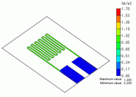
Current running through the wiring can be observed.
To see the results, go to the [Results] tab
and click [Show Numerical Summary Table]  .
.
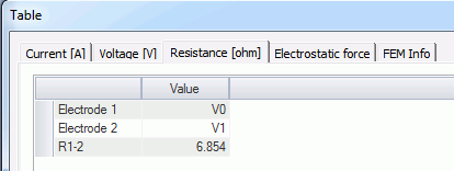
Results of Analysis Model 1 (Before deformation) are as follows.
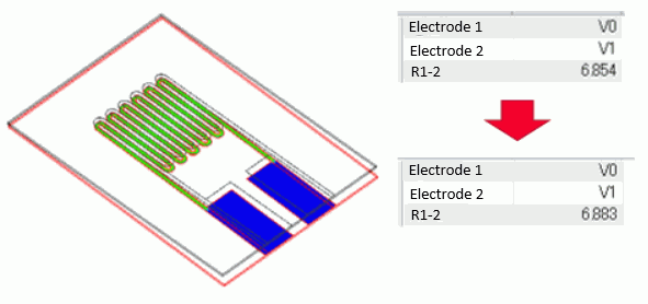
The resistance of R1-2 is 6.854 [Ω].
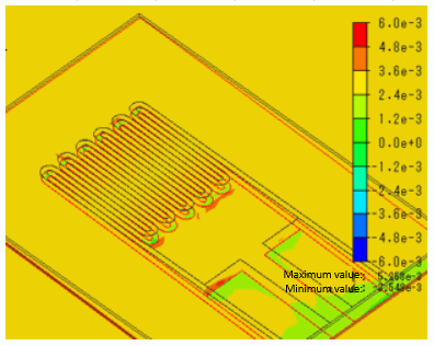
A displacement diagram of Analysis Model 2 (Deformed shape calculation) is shown below. The contour diagram shows the strain perpendicular to the X axis.
The strain is observed on the surface of the substrate due to the bending by the load.
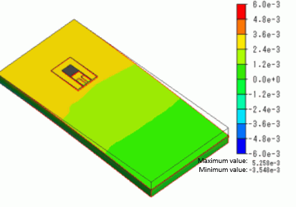
A diagram below shows a close-up of the wiring area.
It can be observed that the strain on the wiring area is almost the same in magnitude as on the substrate surface.
The following contour diagram shows the magnitude of current density of Analysis Model 3 (After deformation).
Displacement diagram setting is ON.
The current in the deformation can be observed.
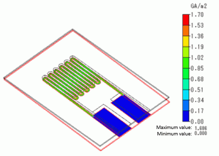
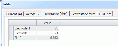
Results of Analysis Model 3 (After deformation) are as follows.
The resistance of R1-2 is 6.883 [Ω]. It confirms that the resistance is increased due to the deformation.