


|
Home / What Femtet Can Do / Details of Analysis Functions / Analysis with Deformed Shape Taken into Account
Analysis with Deformed Shape Taken into Account
Overview
A deformed shape can be taken into account by using a displacement calculated in the stress analysis and piezoelectric analysis.
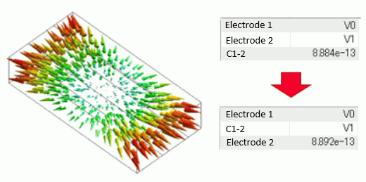
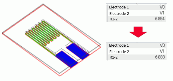
A change in capacitance and resistance due to the deformation can be analyzed.
[Example 1: Capacitance Change by Thermal Expansion]
[Example 2: Resistance Change by Deformation]
This analysis is performed in two stages.
Analysis 1: Stress analysis to obtain the deformed shape
Perform stress analysis to obtain the displacement. Piezoelectric analysis can be used as well.
Analysis 2: Analysis with the deformed shape taken into account
Using the displacement data obtained in the Analysis 1, perform the analysis with the deformed shape taken into account.
Specify the model of Analysis 1 on the [Results Import tab].
 If the results of other project is used for Analysis 1, the results file(.pdt) can be specified for the analysis.
If you want to take a stiffness change, density change, and rotation of the material, as well as deformation, into account, please perform [Analysis with Initial Stress Taken into Account].
Although the analysis may be possible using [Analysis with Deformed Meshes], it is not recommended because there are many restrictions on the analysis setting.
When executing thermal analysis on a model that takes into account the deformed shape of a stress analysis which includes contact boundary, the thermal conduction through the contact face cannot be taken into account.
Procedure
Typical procedure is as follows.
|
Analysis model 1: Before deformation |
Set up the normal analysis condition without taking a deformed shape into account.
|
|
Run the solver with Analysis model 1.
|
|
|
Analysis model 2: Deformation analysis |
Duplicate the Analysis model 1 to obtain the deformed shape. See [Copy Analysis Model into Project] for the details.
|
|
Change the solver of Analysis model 2 to mechanical stress analysis, and set up to obtain a deformed shape.
|
|
|
Run the solver with Analysis model 2.
|
|
|
Analysis model 3: After deformation |
Duplicate the Analysis model 1 to obtain the deformed shape for analysis. See [Copy Analysis Model into Project] for the details.
|
|
Specify Analysis model 2 on the Results Import tab of Analysis model 3.
|
|
|
Run the solver with Analysis model 3.
|
|
|
Results before and after deformation |
Compare the results of Analysis models 1 and 3.
|
Air Domain
For a magnetic or electric analysis that analyzes an air domain with deformed shape taken into account, it may be better to deform the air domain in the stress analysis where the deformed shape is obtained.
Examples are shown below.
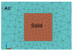
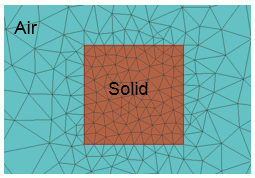
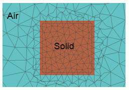
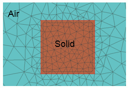
In the examples, a 1mm square solid is expanded by 1% and 10%. The meshes take these deformations into account. The mesh size of the solid is 0.1mm.
If the deformation is small with respect to the mesh size, it will not affect the analysis even if the deformation of the air domain is not calculated.
However, if the deformation is large with respect to the mesh size, irregularity of the meshes will be caused by the displacement of the boundary of solid and air domain, and calculation will not be performed properly.
By calculating the deformation of the air domain, the irregularity of the meshes will not occur. The analysis will be performed normally.
|
Before deformation |
|
|
After 1% deformation / Without deformation of air domain
Mesh size: 0.1mm / Displacement of boundary: 0.005mm |
The displacement of the boundary of solid and air domain is small against the meshes near the boundary. The irregularity of the meshes does not occur. |
|
After 10% deformation / Without deformation of air domain
Mesh size: 0.1mm / Displacement of boundary: 0.05mm |
The displacement of the boundary of solid and air domain is large against the meshes near the boundary. The irregularity of the meshes occurs. |
|
After 10% deformation / With deformation of air domain
Mesh size: 0.1mm / Displacement of boundary: 0.05mm
|
The deformation of the air domain is calculated too. The irregularity of the meshes does not occur near the boundary of solid and air domain. |
If the air domain is taken into account for the stress analysis, set the following settings.
The air domain is regarded as a soft material and its deformation is calculated.
<Automatic creation of the air domain>
・On the [Mesh tab] of the boundary condition, select [Create air domain automatically].
・On the [Mesh tab] of the boundary condition, select [Calculate the deformation of air domain].
<Manual creation of the air domain>
・On the [Analysis Domain tab] of the body attribute of the air domain, deselect [For use in Mechanical Stress Analysis/Galileo].
・On the [High-Level Setting tab], open a dialog box of the setting for stress analysis or piezoelectric analysis. Select [Replace the body out of analysis domain with low-stiffness dummy material]