|
Home / How to Set Body Attribute, Material Property and Boundary Condition / Body Attribute Tabs / Analysis Domain Tab
Analysis Domain Tab
Analysis domains for the body are set up on this tab
It is shown in the [Edit Body Attribute] dialog box. See [How to Set Body Attribute/Material Property].
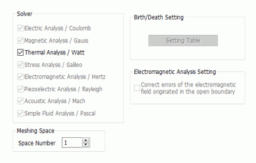
*If Acoustic analysis is selected, an option here will be displayed as [Acoustic Analysis Setting, □Use directivity calculation method]
|
Setting Item |
Notes |
||||||||
|
Solver |
Selectable for each body attribute. In the case of the piezoelectric-acoustic coupled analysis, for example, piezoelectric material should not be used in the acoustic analysis,
|
||||||||
|
Birth/Death Setting |
Sets body birth and death steps in the stress analysis. Available for the multi-step analysis/multi-step thermal load analysis in the static analysis. Refer to [Stress-Static Analysis] of the Technical Notes for detailed birth/death setting.
Prior to the analysis, set up the step analysis on the Step/Thermal Load tab or Step/Thermal Load (Thermal-Stress Coupled) tab.
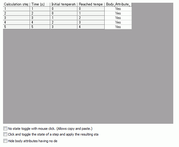
Click the [Setting in Time Table] button. The Time/Step Table window (Birth/Death tab) will appear.
"Yes" means "birth. "No" means "death".
There are 3 setting modes as listed below.
|
||||||||
|
Meshing Space |
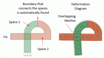
Available for creating overlapping meshes when solving contact in the stress analysis (Example 68 of Stress Analysis).
|
||||||||
|
Rigid Body |
If [Calculate as a rigid body] is selected, all bodies set to the body attribute will be calculated as one rigid body. If there are multiple body attributes that are regarded as rigid, each body attribute will be treated as an independent rigid body. Available only for the stress analysis. The rigid body functions similarly when the rigid face is applied to the entire body. See [Mechanical Tab] for the rigid face and see [Example 73] for the usage.
Caution: A Young's modulus input is required, but regardless of the value, the model is treated as a rigid body for the calculation. |
||||||||
|
Electromagnetic Analysis Setting |
If [Correct errors of the electromagnetic field originated in the open boundary] is selected in the Options for electromagnetic analysis of the analysis condition, the electromagnetic field of the body is corrected. |
||||||||
|
Acoustic Analysis Setting |
Selectable for the acoustic analysis or the piezoelectric-acoustic coupled analysis. Not selected as a default setting. The transient analysis is not applicable for this analysis. If [Use directivity calculation method] is selected, the body field is solved by the directivity calculation instead of the usual FEM. The body must be placed in the opposite side of the driving source across the open boundary. Material must be specified for the body to analyze but if this item is selected, the specified material is not used for the calculation. This is because the peripheral sound field is obtained assuming the material specified with the open boundary condition spreads around the open boundary covering the body.
|