|
Home / How to Set Analysis Condition / List of Analysis Condition Tabs / Step/Thermal Load Tab (Thermal-Stress Coupled)
Step/Thermal Load Tab (Thermal-Stress Coupled)
Conditions for the step/thermal load in the thermal-mechanical stress analysis is set on this tab.
It is in the [Analysis Condition Setting] dialog box. See also [How to Set Analysis Condition].
See Stress-Static Analysis for the details.
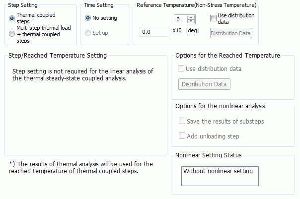
Set up as follows on the Step/Thermal Load tab.
|
Setting Item |
Notes |
|
|
Step Setting |
Sets either Thermal coupled steps or Multi-step thermal load + thermal coupled steps.
Results of the steady-state analysis are used for the reached temperature, and single-step stress analysis is done.
2) If [Thermal coupled steps] and transient analysis are selected for the thermal analysis
Results of the transient analysis are used for the reached temperature, and multi-step stress analysis is done. Setting on the Transient Analysis tab is used for the step setting of the multi steps. (Setting in this dialog box is not needed.)
3) If [Multi-step thermal load + thermal coupled steps] and steady-state analysis are selected for the thermal analysis
The reached temperature is set in this dialog box and multi-step thermal load analysis is done, and then
4) If [Multi-step thermal load + thermal coupled steps] and transient analysis are selected for the thermal analysis
The reached temperature is set in this dialog box and multi-step thermal load analysis is done, and then Setting on the Transient Analysis tab is used for the step setting of the thermal coupled steps. |
|
|
Time Setting |
Sets automatically depending on the thermal analysis type. If it is steady-state analysis, [No setting] is selected, and if it is transient analysis, [Set up] is selected.
To perform creep analysis and viscoelastic analysis, set transient analysis in the thermal analysis and select [Set up] for Time Setting.
* Creep analysis and viscoelastic analysis are available in an optional package. |
|
|
Reference Temperature (Non-Stress Temperature) |
Sets the model's temperature before the thermal deformation. It is assumed that there is no stress at this temperature.
If Use distribution data is selected,
Click the [Distribution Data] button to open the dialog box.
|
|
|
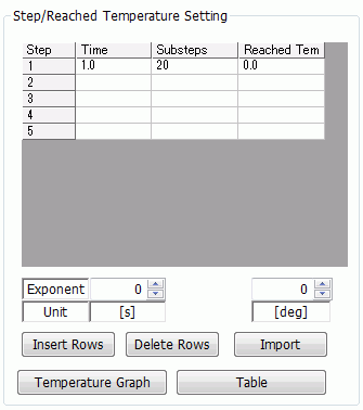
Step/Reached Temperature Setting |
Dialog Box |
|
|
Step |
If [Multi-step thermal load + thermal coupled steps] is selected, any number of steps can be set.
Step numbers in Birth/Death Setting on the Analysis Domain tab and [ON/OFF Setting] on the Mechanical tab correspond to the steps on this table.
If [Multiple steps] is selected for Step Setting, and [No setting] is set for Time Setting,
|
|
|
Time |
Available if [Set up] is selected for Time Setting.
A real number 0 or greater is acceptable. The start time of each step is the end time of the previous step. The start time of step 1 is zero. The end time must be a positive real number.
If [Multiple steps] is selected for Step Setting, and [Set up] is selected for Time Setting,
|
|
|
Substeps |
Available if [Thermal coupled steps] and steady-state analysis are selected for the thermal analysis, and nonlinear analysis (large deformation, contact, nonlinear material) is set for the mechanical stress analysis.
Sets the number of substeps for each step. This setting will affect the accuracy and convergence of the nonlinear analysis.
If you want to output the results of substeps, select [Save the results of substeps].
|
|
|
Reached Temperature |
Sets the temperature at the end time of each step.
Temperature changes linearly over the steps.
If [Multi-step thermal load + thermal coupled steps] is selected for the step setting, you can view the time-temperature graph by pressing [Temperature Graph] button.
|
|
|
Table |
Opens Time/Step Table window. The following are displayed on the table.
If [Thermal coupled steps] is selected for Step Setting, and steady-state analysis is set for the thermal solver and nonlinear analysis is set for the stress solver, you can compare the load set on the Mechanical tab and the actual load reflected in in each substep.
If [Multi-step thermal load + thermal coupled steps] is selected for Step Setting, 1) Birth/Death of each body attribute set on Analysis Domain tab. 2) Material Change of each body attribute set on Material Change tab. 3) ON/OFF of each boundary condition set on Mechanical tab. 4) Weight Function of each boundary condition set on Mechanical tab. See [Weight Function Setting].
1), 2), and 3) are editable on the table.
|
|
|
Options for the Reached Temperature (Steady-State Thermal Analysis/Thermal Coupled Steps Only) |
Use Distribution Data |
Not available for the thermal-stress coupled analysis. |
|
Options for the Nonlinear Analysis (Steady-State Thermal Analysis/Thermal Coupled Steps Only) |
Save the Results of Substeps |
Outputs the results of substeps. |
|
Add Unloading Step |
Adds a second step to return from the reached temperature of the first step to the reference temperature. |
|
|
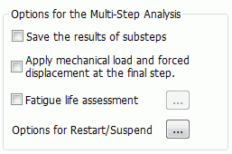
Options for the Multi-Step Analysis |
Dialog Box |
|
|
Save the Results of Substeps |
Outputs the results of substeps. |
|
|
Apply Mechanical Load and Forced Displacement |
Usually, mechanical load and forced displacement are applied from the first step.
|
|
|
Fatigue Life Assessment |
Sets options for the fatigue life assessment. * Fatigue life assessment is available in an optional package.
If [Fatigue life assessment] is selected, the fatigue life of the model is predicted. This prediction is based on Manson-Coffin law.
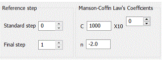
[Reference Step] sets the standard step and the final step to obtain the equivalent inelastic strain amplitude from the accumulated equivalent inelastic strain of the multi-step analysis. [Standard step] accepts an integer 0 or greater but smaller than the maximum step number. [Final step] accepts an integer greater than 0 up to the maximum step number.
[Output the results of standard and final steps only] reduces the size of the result file.
Coefficient of Manson-Coffin Law's sets the coefficient of Manson-Coffin law's to calculate the life from the equivalent inelastic strain amplitude.
Manson-Coffin law Nf = C Δεne^n where Nf is the fatigue life (unit: cycles). Δεne is the equivalent inelastic strain amplitude (unit: %)
C is the fatigue life when the equivalent inelastic strain amplitude (Δεne) is 1%. An integer greater than 0 is acceptable. n is the influence parameter of Δεne. A negative real number smaller than 0 is acceptable.
Refer to [Fatigue Life Assessment] of the Technical Notes for details. |
|
|
Options for Restart/Suspend |
Not applicable to the thermal-stress coupled analysis. |
|
|
Nonlinear Setting Status |
Tells you if the analysis is nonlinear.
- Without nonlinear setting Substep setting is not required.
- With nonlinear setting Substep setting is required. Substeps will affect the accuracy and convergence of the analysis. |
|
 Time setting takes effect in the creep analysis and the viscoelastic analysis.